How do they make the OPA388 with "no 1/f noise" (in fact constant from 0.1Hz to 10Hz). There must be some correlator inside, otherwise physics would cry out loud.
it is a chopper amplifier, the dc noise gets mixed up to the chopper frequency.
How do they make the OPA388 with "no 1/f noise" (in fact constant from 0.1Hz to 10Hz). There must be some correlator inside, otherwise physics would cry out loud.
Right, like correlated double sampling in a CCD.
... an unsnubbed Triad FS24-800 oscillated in operation at 26kHz when attached to a W01 bridge rectifier, and at 21kHz with a 4x1N4004 bridge. Using the ringer, I obtained 86kHz on the bench.
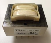
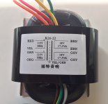
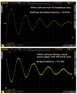
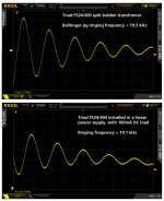
I tried a similar experiment this morning, using three different transformers. #1 was the 15VAC, 500 mA wall wart shown in post #91086. #2 was a Triad FS24-500 split-bobbin transformer, shown in image 1 below. #3 was an Rcore transformer I bought from seller "DIYaudiokit" on eBay, shown in image 2 below.
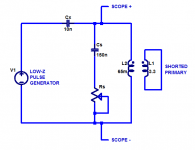
First I tested each of the three transformers on a bellringer test jig, whose simplified schematic is image 3 below. I set the DSO to measure the ringing frequency, it's displayed at bottom left of the scope photos.
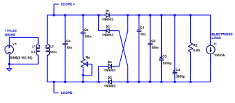
Then I installed each of the transformers into my test board / linear power supply, with 100mA DC load connected. The schematic of this arrangement is image 4 below.
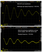
My results are shown in images 5, 6, and 7. To summarize:
Code:
                    Bellringer     Linear PSU
                    jig ringing    ringing
     Transformer    Frequency      Frequency
  ==========================================
      15VAC wart     33.8 kHz      31.3 kHz
  Triad FS24-500     19.5 kHz      19.1 kHz
   R_core R26-22     69.6 kHz      70.4 kHz
_
Attachments
Mark, about capacitors, would a MLCC type like 810-FK28C0G2E151J (C0G (NP0) (Mouser part number) be applicable for the purpose of snubbing, or would it be better to select a 'Poly' type (or maybe other). Any ideas on this?
Mark,
I see a serious problem with your R core transformer. It use a green wire for a primary conductor. To me that makes it unacceptable.
ES
I see a serious problem with your R core transformer. It use a green wire for a primary conductor. To me that makes it unacceptable.
ES
Code:
I tried a similar experiment this morning, using three different transformers.Thank you for your measurements.
I must get to the bottom of this, so I'll redo my tests and report back.
Regards,
Braca
Mark, about capacitors, would a MLCC type like 810-FK28C0G2E151J (C0G (NP0) (Mouser part number) be applicable for the purpose of snubbing, or would it be better to select a 'Poly' type (or maybe other). Any ideas on this?
Besides avoiding math altogether, the really great thing about tuning a snubber while observing the ringing on an oscilloscope is: you actually see with your own eyes, exactly what you're getting! If an inferior snubbing capacitor is causing misbehavior: you'll see it! Your scope trace is zoomed in upon the exact fine-grained behavior that matters. If you like what you see, yer done. If a capacitor made with lead alloy plates and gutta-percha dielectric gives pleasing waveshapes: be pleased. Yer done.
Me personally, I tend to prefer a certain line of EPCOS film capacitors for snubber use (Quasimodo design note p.7) because their loss angle (tan δ) is small. Some people feel that safety-rated X capacitors are a good idea for across-the-secondary use {Cx in #91143}; these folks think that if the mains voltage spikes from 230VAC to 2300 volts, the secondary will spike 10X as well, and you don't want your across-the-secondary capacitor Cx to pop. On the other hand, if the secondary is connected to a bridge rectifier which drives BIG filter capacitors, half of the bridge will be forward biased and it will simply connect the surge to the filter caps. This will conduct ENORMOUS currents that either blow the fuse, or blow the filter capacitors, or both. But in either case the snubber cap doesn't see 2300 volts so it will survive the carnage just fine. 🙄 Half wave rectifier circuits don't have this nice property.
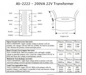
How do you feel about green wires connected to the secondary? PassDIY and diyAudio preferred vendor Antek routinely uses green wires for secondary connections, see image below.I see a serious problem with your R core transformer. It use a green wire for a primary conductor. To me that makes it unacceptable.
_
Attachments
It was probably something silly like a not-shorted winding during bellringer tests, caused by an alligator clip that slipped off, or a piece of masking tape that came loose.I must get to the bottom of this, so I'll redo my tests and report back.
Since the ringing engages the complete magnetic structure of the transformer you should see the ringing in the mag field around the transformer. Do you see it? A fast changing magnetic field will get into a lot of stuff.
green-yellow is the unambiguous standard for Safety Ground/Protective Earth
solid green; maybe/maybe not
https://en.wikipedia.org/wiki/IEC_60446
solid green; maybe/maybe not
https://en.wikipedia.org/wiki/IEC_60446
Since the ringing engages the complete magnetic structure of the transformer you should see the ringing in the mag field around the transformer. Do you see it? A fast changing magnetic field will get into a lot of stuff.
Gerber format CAD files for my test board are attached to post #91058. Please feel free to build one or more boards and make all the measurements you desire. The file name extensions are set to OSH Park's standard; if you need a different set of file extensions (e.g. for Elecrow or seeed or some other PCB fab), just let me know. I will run a simple MSDOS .BAT script that executes the REName command once for each PCB layer.
This has been a very good thread about transformer ringing and how to lower it. I have used Mark and Ed's ideas for many years with good results. I hope the discussion continues.
green-yellow is the unambiguous standard for Safety Ground/Protective Earth
solid green; maybe/maybe not
https://en.wikipedia.org/wiki/IEC_60446
Yes green-yellow is used for safety conductor according to IEC and neither green or yellow should be used anywhere. It is not like there aren't enough colors.
Green is used in the NEC for the safety conductor.
Mark,
I don't want green anywhere really but it is okay for a shield if the design runs out of solid color conductors. Red - Green color blindness can still be an issue. Not so much Blue - Yellow or even total color blindness as the folks affected usually are aware of the issue.
We can easily calculate the total effective leakage inductance (of the secondary + reflected leakage inductance of the primary), starting from the RLC circuit's ringing frequency. Recall that
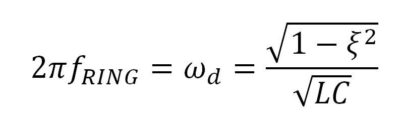
In the bellringer test jig with Rs = Infinity (removed from socket), the damping ratio zeta is much much less than 1. A numerically convenient approximation is (zeta = 0). Plugging that into a calculator, along with the information that the bellringer's parallel capacitance Cx was 10nF, gives these results:
Code:
                                   Extracted
                    Bellringer     Leakage
                    jig ringing    Inductance
     Transformer    Frequency      (Cx=10nF)
  ==========================================
      15VAC wart     33.8 kHz      2.22 mH
  Triad FS24-500     19.5 kHz      6.66 mH
   R_core R26-22     69.6 kHz      523  uH
Attachments

Yes green-yellow is used for safety conductor according to IEC and neither green or yellow should be used anywhere. It is not like there aren't enough colors.
Green is used in the NEC for the safety conductor.
Mark,
I don't want green anywhere really but it is okay for a shield if the design runs out of solid color conductors. Red - Green color blindness can still be an issue. Not so much Blue - Yellow or even total color blindness as the folks affected usually are aware of the issue.
Yes, but can you tell the diff between green and green/yellow at the bottom of the trench to disarm the nuke using only a lumistick?
John
Yes, but can you tell the diff between green and green/yellow at the bottom of the trench to disarm the nuke using only a lumistick?
John
Trick question! Of course, you just tap each wire lightly because as all true àudiophiles know striped wire sounds different. 🙂
Slightly off topic.
I did not realise that there is actually an optical phono cartridge as product.
DS002 ?NEW?
It is not ridiculously expensive.
Patrick
I did not realise that there is actually an optical phono cartridge as product.
DS002 ?NEW?
It is not ridiculously expensive.
Patrick
Not the first but the first in a long time. Many interesting odd ideas in the past. There was a cartridge that connected the cantilever to the grid of a tube.
They don't all work equally well but the more the merrier.
They don't all work equally well but the more the merrier.
- Status
- Not open for further replies.
- Home
- Member Areas
- The Lounge
- John Curl's Blowtorch preamplifier part II