"Impedance protected" means there is enough leakage inductance by design to limit primary current to a safe value even if the secondary if shorted.
How long a transformer rings is a function of its Q, where winding and core losses dissipate stored energy in transformer fields.
A common way to figure out transformer inductance and capacitance is to sweep it or ping it to find the resonate frequency, then connect an external capacitor and see how much that lowers the frequency. Sometimes other windings are shorted or left open to figure out their contribution. Solving the resulting simultaneous equations, etc., gives transformer equivalent lumped inductance and capacitance. Good article with lots of details here: http://www.nascentechnology.com/pdf/extracting_transformer_parameters.pdf Also: http://www.pe.org.pl/articles/2012/9a/3.pdf And for anyone interested a more academic treatment: http://citeseerx.ist.psu.edu/viewdoc/download?doi=10.1.1.426.186&rep=rep1&type=pdf
Last edited:
I find that when extracting circuit parameters from measurement data, solving N equations in N unknowns does not give as robust an answer as "solving" (3*N) equations in N unknowns. I.e. take lots and lots of data points and then perform least squares optimization to find the values of the N unknowns which give the smallest RMS error. This reduces the effects of outlier datapoints and not-very-accurate measurement equipment / procedures.
The "trendline" feature in Excel will do a least squares fit and display the equation and the R-squared value right on the plot. Beware that its definition of error is (yfitted - ymeasured)^2 which implicitly weights large values more than small values. If instead you want to minimize percentage error ((yfitted - ymeasured)/ymeasured)^2 you'll need to switch over to the "Solver" in Excel.
The "trendline" feature in Excel will do a least squares fit and display the equation and the R-squared value right on the plot. Beware that its definition of error is (yfitted - ymeasured)^2 which implicitly weights large values more than small values. If instead you want to minimize percentage error ((yfitted - ymeasured)/ymeasured)^2 you'll need to switch over to the "Solver" in Excel.
One thing about ferrite core transformers and inductors is that the core permeability is subject to change with temperature, time, and other factors. Therefore, depending on the application, it may or may not be useful to put a lot of effort into making highly accurate measurements. That being said, using gapped cores can help stabilize core properties a lot, to the extent air gap reluctance dominates total magnetic circuit reluctance.
Last edited:
The subject of transformer modelling for this purpose was dealt with in some detail in the excellent paper by Morgan Jones in Linear Audio Vol. 5 (I apologize if it has already been mentioned in this thread).
My limited experience in the small-signal area indicates that a simple model may be ample in most cases.
Using the Quasimodo "ringer" proposed by Mark Johnson I tested 15 small transformers (< 20VA) and a 380VA one in order to determine the snubber resistance value for the damping value of 0.707. In addition, I recorded the natural frequency of the parasitic inductance with a 10nF capacitor across the secondary, the secondary resistance, and the natural damping coefficient from the logarithmic decrement of the oscillation decay.
The results were entered into an Excel sheet and compared with the Hagerman's formula, which takes the parasitic inductance, secondary resistance, and the total capacitance present at the secondary as input, and calculates the snubber resistance for the desired damping factor.
The results are summarized in the attachment. Referring to the columns labeled "Rs @ Zeta,opt [QModo]" and "Rs @ Zeta,opt [calc]" it is seen that there is a good agreement between the former, i.e. experimentally determined, and the latter, i.e. calculated, snubber values.Limiting the error bound to +-20%, in 12 out of 15 small transformers the agreement between the two values was between -6.6% and +18.2%.
I also checked several of the above transformers in operation and under load. In all cases the desired damping was achieved with higher snubber resistances (up to a factor of two) than determined on the test bench. In other words, the values obtained by means of the ringer test are on the conservative side.
The last row in the table contains the Hagerman formula: on entering the secondary resistance and the natural frequency with the capacitance Cx (currently 10nF), the last cell displays the snubber resistance for the damping coefficient specified in the cell to the left of the former.
If there is interest, I will post the Excel sheet as well. An older version of the table is available in post #760 on the link below:
http://www.diyaudio.com/forums/powe...rmer-snubber-using-quasimodo-test-jig-76.html
Regards,
Braca
Attachments
Have you posted scope photos of the same transformer and snubber exhibiting (damping behavior X) in bench testing, followed by (damping behavior not-X) when installed in the final audio gear? Where can we view these?
Another sidestep that should generate some interest:
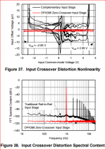
The new OPA388 is touted as having 'no input crossover distortion'. They claim that complementary input stages (you know, the upside-down P- and N-LTPs) have input crossover distortion. This config is found in rail-to-rail input opamps.
The OPA388 circumvents this by having an integrated charge pump so they have additional supply to do R-R input without having to resort to complementary LTPs.
Question: how credible is this? Has anybody ever tried to measure the 'input crossover distortion' of complementary input stages? If this is real it has obvious implications for complementary audio input stages.
TI did, see attached.
Jan
Attachments
OTherefore, depending on the application, it may or may not be useful to put a lot of effort into making highly accurate measurements. .
One could argue that audio is not one of them tho! The quasimodo approach gets you 90%+ of the way there with a very simple test jig and saves all the audiophile angsting over which diodes to use and where to put snubbers.
In terms of a real benefit to the DIY crowd that LA article on snubbing is a real boon. Of course for line level work the silentswitcher takes it to a whole new level.
not relevant, audio comp diff pair both operate continuously
rail-rail input op amp switch form using one diff pair to the other as their inputs approach a rail
rail-rail input op amp switch form using one diff pair to the other as their inputs approach a rail
Question: how credible is this? Has anybody ever tried to measure the 'input crossover distortion' of complementary input stages? If this is real it has obvious implications for complementary audio input stages.
not relevant, audio comp diff pair both operate continuously
rail-rail input op amp switch form using one diff pair to the other as their inputs approach a rail
When you look at those graphs it happens as the CM input voltage goes through zero, not so much as the input voltage approaches the rail.
If you imagine an audio input stage with the input to one side of the (complementary) LTP, the feedback to the other, the 'input crossover' would then coincide with input signal zero crossing (assuming negligible phase shift).
Jan
When you look at those graphs it happens as the CM input voltage goes through zero, not so much as the input voltage approaches the rail.
The exact transition point is not really important, but in general I would not worry about this the designs you see for audio amps do not commutate the tail current (and they don't go to the rails either). We have apples and oranges performance goals here.
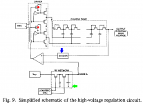
Aaaaaaand, it's unexciting.
The big innovations were
_
The big innovations were
- (red): disabling the clock driver when the charge pump output voltage is high enough
- (blue): on an NMOS EPROM process that does not include resistors, building a precise voltage divider using switched capacitors
- (green): implementing a long, long timeconstant lowpass filter using switched capacitors. You can get fast wake-up at power on by turning on both switches, temporarily making an RC lowpass filter with R=zero.
_
Attachments
Last edited:
The exact transition point is not really important, but in general I would not worry about this the designs you see for audio amps do not commutate the tail current (and they don't go to the rails either). We have apples and oranges performance goals here.
So these stages in opamps run in class AB, sort of?
I posted several screenshots from the tests I made in a running power supply here:Have you posted scope photos of the same transformer and snubber exhibiting (damping behavior X) in bench testing, followed by (damping behavior not-X) when installed in the final audio gear? Where can we view these?
http://www.diyaudio.com/forums/powe...-using-quasimodo-test-jig-74.html#post4530680
Unfortunately, I did not save the oscillograms obtained on the test bench; however, they differ from the "in situ" only ones in terms of the parasitic oscillation frequency. Referring to post #740 on the above link, an unsnubbed Triad FS24-800 oscillated in operation at 26kHz when attached to a W01 bridge rectifier, and at 21kHz with a 4x1N4004 bridge. Using the ringer, I obtained 86kHz on the bench.
Since the recitifier capacitance is small in comparison with the 10nF capacitors which I had strapped across each of the two secondaries, it appears that the parasitic inductance was somehow not the same in the two configurations (if I didn't make a mistake when I did the test a year ago, that is).
Regards,
Braca
Not really. It's more like "avoidance of gm-doubling". See figure (MC33201 opamp)So these stages in opamps run in class AB, sort of?
Q1 is the evil bastard who causes "input crossover distortion".
If the common-mode input voltage is very low, the PNP input pair Q6-Q7 is active. Their emitter ("tail") node is so low that Q1 is OFF. With no collector current in Q1, transistors Q2-Q3 are also OFF, and so the NPN input pair Q11-Q12 are OFF too.
Now suppose the common-mode input voltage is high, so high that Q6-Q7's "tail" node is high enough to turn on Q1. Q1 steals the tail current from Q6-Q7 and directs it into the Q2-Q3 mirror, where it becomes tail current for the NPN input pair Q11-Q12.
Aha, we have avoided gm-doubling by ensuring that only one of the two long-tail pairs is ON and we have forced the other to be OFF.
BUT!! What happens at the transition? "Input Crossover Distortion" that's what!
Yes, yes, this example is bipolar but Jan's datasheet is about a CMOS opamp. The same thing is happening in both cases but I figured you old, tired, burned-out, dont-make-me-think, bipolar guys would prefer to look at a bipolar schematic. If not, or if you don't trust me, please feel free to pull up a CMOS RRIO opamp schematic your own self. You'll find an evil bastard MP1 that steals tail current from a PMOS long tailed pair and sends it to an NMOS long tailed pair.
Attachments

Last edited:
Not really. It's more like "avoidance of gm-doubling". See figure (MC33201 opamp)
Jan needs to qualify "op-amps" for this discussion. Op-amps with fully complementary inputs presented here usually have tail currents that are constant, not switched, and have no pretentions of going to either rail. Totally different beasts than those designed for R to R IO.
The OPA388 story specifically targets RR input opamps as having in general input xover distortion because they have complementary LTPs, which they need to be input RR (their words, not mine) which they say the OPA388 gets rid off.
I then thought about the audio amps that sometimes use complementary input LTPs with the argument that they are 'symmetrical' and by implication more linear; I was wondering whether those input stages might have a similar issue. It appears not, thank Ohm!
Jan
I then thought about the audio amps that sometimes use complementary input LTPs with the argument that they are 'symmetrical' and by implication more linear; I was wondering whether those input stages might have a similar issue. It appears not, thank Ohm!
Jan
- Status
- Not open for further replies.
- Home
- Member Areas
- The Lounge
- John Curl's Blowtorch preamplifier part II