Article has appeared on EDN
The G word: How to get your audio off the ground | EDN
(for some reason it does not show the pics for me today)
And it was also available as pdf from hypex.nl website, but that link seems broken also.
The G word: How to get your audio off the ground | EDN
(for some reason it does not show the pics for me today)
And it was also available as pdf from hypex.nl website, but that link seems broken also.
Dear All,
I intend to assemble the board I received with Linear Audio. I want to see if my reading of the article, plus the thread was fruitful:
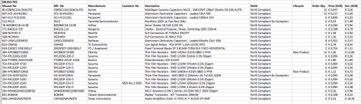
The BOM I intend to use is attached: is it correct ? I think it incorporates the Oops from linear audio.
I will use a 12+12 V transformer and the Hypex regulators.
I will make a run of Hans boards (Not the ones for the controller) if nobody has a spare for me.
As I understood Hans board is controlled pulling low or high four pins from 0000 to 1111. I was thinking to do this with an arduino and rotary encoder/remote. Is there a smarter/simpler way ? I understand that the value of high depends by the relay used, so I should be able to control directly 5V relay with a 5V arduino.
Anything else I am missing ?
Thanks,
Davide
I intend to assemble the board I received with Linear Audio. I want to see if my reading of the article, plus the thread was fruitful:
The BOM I intend to use is attached: is it correct ? I think it incorporates the Oops from linear audio.
I will use a 12+12 V transformer and the Hypex regulators.
I will make a run of Hans boards (Not the ones for the controller) if nobody has a spare for me.
As I understood Hans board is controlled pulling low or high four pins from 0000 to 1111. I was thinking to do this with an arduino and rotary encoder/remote. Is there a smarter/simpler way ? I understand that the value of high depends by the relay used, so I should be able to control directly 5V relay with a 5V arduino.
Anything else I am missing ?
Thanks,
Davide
Attachments
I reworked my BOM starting with the original article. In the file previously posted there were some expensive resistors where apparently were not needed.
Are the gerber for Hans Polak board (published on LA website) available ?
Did I get the controlling strategy correctly ?
Thanks,
Davide
Are the gerber for Hans Polak board (published on LA website) available ?
Did I get the controlling strategy correctly ?
Thanks,
Davide
Attachments
I intent to power mine through a SilentSwitcher, which seems the perfect solution for this. It would allow the pre-amp to run of batteries if wanted 🙂
It was discussed earlier in the thread some pages back. You wouldn't need the Hypex regulators then 🙂. Here's a link to the product: https://linearaudio.nl/silentswitcher
Brgds, Rene
It was discussed earlier in the thread some pages back. You wouldn't need the Hypex regulators then 🙂. Here's a link to the product: https://linearaudio.nl/silentswitcher
Brgds, Rene
Wondering what might be workable using a Goldpoint switched volume control.
An externally hosted image should be here but it was not working when we last tested it.
Wondering what might be workable using a Goldpoint switched volume control.
An externally hosted image should be here but it was not working when we last tested it.
What about having a 5K linear pot, in serie with a couple of good 5K resistors ?
That would give less gain, and more flexibility for attenuation, right ?
JMK
Help please
1. I'm using the Maya controller. On the widely circulated diagram showing the Maya / BPBP set up, the connection between the Maya Controller and the VolCB board shows a 6 pin connection at the VolCB end, but at the Maya end it shows a 9 pin connection! Is that a mistake in the graphic? I can see the corresponding 6 pins on both the VolCB and the Maya - are the other 3 on the Maya redundant when using this configuration?
2. I have a 12-0-12v trafo to power the BPBP. Is the middle pin on the power input header on the BPBP the 0v pin?
There are two "net tie" connections to 4 & 10.
That makes 8 wire connections.
Where is the ninth?
The Putzeys' PCB has a single bridge rectifier designed for connection to a centre tapped transformer.
The three power connections are located together ~,CT,~
Unfortunately the three holes are not labelled. But turn the PCB over and you will see the CT (middle hole) goes to the smoothing capacitors' Zero Volts.
There are two "net tie" connections to 4 & 10.
That makes 8 wire connections.
Where is the ninth?
QUOTE]
You are referring to the BPBP to Vol CB connection, but I'm referring to the VolCB to Maya Controller controller connection. Thanks for the other info re CT.
What about having a 5K linear pot, in serie with a couple of good 5K resistors ?
That would give less gain, and more flexibility for attenuation, right ?
JMK
You really should read the article (or earlier in this thread) why this is not a good idea. The whole concept of doing vol control this way is explained.
Also explains why Bruno chose to do the vol control this way and accept that you cannot turn it all the way up or down.
Jan
Apologies if I'm being stupid... Can someone clarify if the "net tie" points on the PCB need to be populated with a wire link? I've read comments on here suggesting that you should do so, and obviously do so early in the component stuffing phase to make the soldering job easier, but I've seen pictures built and supposedly working boards with nothing soldered at the points I think are the "net tie" points. A quick buzz with my meter suggests that these points are electrically connected - presumably on the other side of the board, though the traces are challenging my ageing eyesight.
The net tie points are plated through holes that the simulation software requires to isolate parts of a circuit from others and yet remain connected. B.Putzeys describes this in his paper.
1. I'm using the Maya controller. On the widely circulated diagram showing the Maya / BPBP set up, the connection between the Maya Controller and the VolCB board shows a 6 pin connection at the VolCB end, but at the Maya end it shows a 9 pin connection! Is that a mistake in the graphic? I can see the corresponding 6 pins on both the VolCB and the Maya - are the other 3 on the Maya redundant when using this configuration?
You are right. The left 3 pins are redundant.
Hans
The net tie points are plated through holes that the simulation software requires to isolate parts of a circuit from others and yet remain connected. B.Putzeys describes this in his paper.
That was what I thought (from reading the paper) so I don't need to do anything with them myself, which is a relief.
hypex-preamp-Bom.pdf - I can't remember where I downloaded this document from, but I'm sure it was from this thread or one of the group buy threads. It lists the capacitors like this:
C10, C16, C26, C27, C28, C29 C12, C13, C14, C15 - Electrolytic Capacitors ‐ Leaded 22uF 100V 20% Audio SILMIC II Aluminium Electrolytic
and
C12, C13, C14, C15 - Capacitors ‐ Leaded 1000uF 25V 20% Audio SILMIC II
I ordered these from Mouser, and they are all very large, and don't really fit the board. I've made them fit by "flying" them above the adjacent relays, and hanging them from the edge of the PCB, and leaning the regulators over at a crazy angle. It's all connected, but its far from pretty.
So, when ordering the capacitors, check the physical sizes carefully.
You are right. The left 3 pins are redundant.
Hans
for the avoidance of doubt: "left" when looked at from the rear of the Controller i.e. the ones marked SST, SPK and STD - yes?
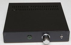
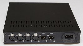
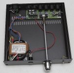
Here is my take on the BPPBP. I have taken the minimalist view, just all I need. Case from the DIY Audio shop.
I have been listening through it for the past few days, audio files are .flacs and the amp is a Pass diy F4. Dead quiet, very neutral to my ears, sparkling highs. My other preamps are a Pass diy BA3 and Doug Self opamp pre.
I am happy to add this BPPBP to my collection. Thank you Bruno and the other folks that brought it to fruition.
David
Attachments
- Home
- Source & Line
- Analog Line Level
- BPPBP - Bruno Putzey's Purist Balanced Preamp (well a balanced volume control really)