I thought about that afterwards and agree. I think an AT 93 has 10 metres of wire per bobbin ( we ran across the road unwinding one ). I didn't find the one I wanted to test yet. I usually find it every time I go looking for nuts and bolts. It's moved. Friends don't have any either.
More SSL triva. They did use NE5532 and NE5534. John says NE5534 could have been 1 million pieces a year. John left before the use of newer op amps. He says he didn't like the SSL desks as they obviously changed the sound, others at SSl thought the same. Less real he says. All the same 92 x 5534 is a long signal path so not bad. John also said there were ways to simplify the use of the desk to get better sound which could be taught. The customer advantage of SSl was to be very quick to set or reset ( from the inbuilt memory ). A typical use might be TV adverts made as quickly as possible. The people who did that had no time to get it perfect. The skill was to get it nearly perfect first time. A production line really.
More SSL triva. They did use NE5532 and NE5534. John says NE5534 could have been 1 million pieces a year. John left before the use of newer op amps. He says he didn't like the SSL desks as they obviously changed the sound, others at SSl thought the same. Less real he says. All the same 92 x 5534 is a long signal path so not bad. John also said there were ways to simplify the use of the desk to get better sound which could be taught. The customer advantage of SSl was to be very quick to set or reset ( from the inbuilt memory ). A typical use might be TV adverts made as quickly as possible. The people who did that had no time to get it perfect. The skill was to get it nearly perfect first time. A production line really.
kgrlee said:Did you actually measure OP27 with a real cartridge Wayne?
I replaced OP27 in a commercial product with 5534 and got a dB or more improvement in real life noise IIRC.
I just measured an OP270 (Ib-compensated essentially a dual OP27) and compared it to some various op amps.
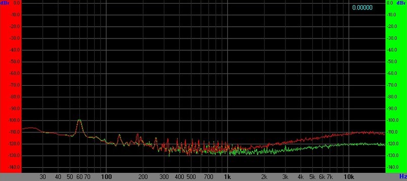
The following FFTs are with the balanced input preamp in the FLAT, non-RIAA, mode to reveal the HF differences which are quite small. I compared the noise level with identical op amps to make sure the curves overlaid then mounted one op amp in the left and a different op amp in the right. The source is a Stanton 681EE, on a turntable, located a few feet from a dimmer.

Flat Balanced Input Preamp, OP270 Green, OPA1642 FET Red

Flat Balanced Input Preamp, OP270 Green, NJM2068 Red

Flat Balanced Input Preamp, OP270 Green, NJM5532 Red

Flat Balanced Input Preamp, OP270 Green, LME49720 Red
The OP270 is actually pretty respectable for a MM input. With the preamp input balanced in an instrumentation amp topology the low Ib doesn't provide any significant benefit since the "Ios" of dual op amps (between different op amps in the same package) is quite small based on experience. I left the OP270s in to listen to them.
This concern over bias current is way, way overblown. You guys worry too much.
And yes SSL do use NE5532s but the 5534 had the volumes back when SSL4000 and SSL6000 had typical frame sizes of 48-60 modules. In later product (the 9K) they began to use 5532s about the time frame sizes began to shrink.
And the ONE example we now have of a cart being blown is someone who hooked the supply up backwards. Why am I not surprised...I put 1N4004 reverse polarity clamp diodes on the preamp power rail just for him. Saw that one coming.
Oh and lest I forget: The cartridge lines to the preamp input are shielded twisted pair. When I unbalance the instrumentation amp at the input I can see huge differences in HF hash on that channel with the cover off. Yeah this balanced thing is total BS.[/SARC]
Last edited:
This concern over bias current is way, way overblown. You guys worry too much.
What else is new, BTW from John Curl himself the MA-332 family was really selected Raytheon 5534/2's considered the best by some. The folklore has a way of just propagating, for every story there a complementary one.
The balanced/unbalanced thing is a combination of not invented here and requiring user intervention to unground the shorted pin on the cart is just simply not done, ever, period. I think you wanted the 🙄
Last edited:
I can't see your plots clearly - you are showing dBr (dB Relative?) - is that ref 2V FS on the sound card? Can you share how many averages you have done?
96 kHz SR, 32 kpts, avg=10, 0 dBFS approx +8dBu/2V rms.
Note that the preamp output does not have RIAA EQ applied.
1 kHz 3.54 cm/second (L or R only modulation equivalent to 5 cm/sec lateral) produces -23 dBFS. (This gives a headroom of about 4-6 dB for flat recordings.)
The A-weighted noise with RIAA EQ (not shown) is just shy of -99 dBFS with the OP270s which are what not I normally use. IIRC I measured about -95.5 dBFS with the OP270s, no weighting. (The measurement bandwidth is - I think - Fs/2 since I'm not using an external or internal filter.)
There's no magic in this circuit other than it's wired with shielded twisted pair cart connections, has balanced in/out, and common mode rejection is realized with "double-balanced" (cross-coupled) line receivers. I followed a no BS approach having given up worrying about input bias current around 2011.
nigel pearson said:Below is approximately the workings of NE5534. I have always assumed the transistor bases would die first.
The back-to-back input diodes (differential clamp) may also short and exist in many NPN input audio op amps. (NE5532/5534 NJM2114 LME49710/20 OPA1612 etc.)
What you don't see in that simplified schematic are ESD diodes from input/output pins to rails. Under fault conditions they typically short and do provide a low resistance path to the supply rail with current limited by the cart DCR. At t=0 the peak current is the same regardless of whether a coupling capacitor is in the input or not.
scott wurcer said:requiring user intervention to unground the shorted pin on the cart
I would hope everyone is aware how insanely easy that is. Those little ground clips are designed to slide off the pin and are only wedged between the shell and body. With a small pick, needle or straight pin it takes about 5 seconds. Reinstalling one takes slightly longer but not much.
I'm learning that many cables which appear to be coaxial are actually shielded twisted pair up to the molded RCA. The stupid RCA itself (and the preamp input) is often the sole bottleneck to a floating balanced interface.
Last edited:
Richard, I didn't know you worked with Eric. I have two of the very few Zucharelli Holophonic recordings, they are scary good through headphones. Never played with ambisonics.
Horowitz & Hill have a 70pV/rtHz amp (I think) in the new 3rd ed. of The Art of Electronics. They point to some devices that have even smaller rbb' than the old Hitachi / Toshiba / etc devices that are now Unobtainium.
Dunno how good it would be for a real life MC
Eric & I were planning a transformerless active ribbon using my little circuit. But even with my circuit, (which uses current more efficiently than other topologies) I jibed at the possibility of the 63mA which was required for 3dB NF @ 0R2 running through the ribbon.
____________
Wayne, my dislike for EVIL Ib cancelling is mainly for stuff that has very different Z on +/- OPA input pins. Possibly the worst case is a single OPA RIAA MM stage.
I use Ib cancelling OPAs in certain stuff .. including my Yahoo MicBuilders LNprimer.doc ... though it wasn't ideal.
Apologies to those who can't get at that but you have to join. I'm ricardo there.
____________
Evil! EVIL!!!! Probably the most unreliable 5534/2s ever made.BTW from John Curl himself the MA-332 family was really selected Raytheon 5534/2's considered the best by some.
kgrlee said:Wayne, my dislike for EVIL Ib cancelling is mainly for stuff that has very different Z on +/- OPA input pins. Possibly the worst case is a single OPA RIAA MM stage.
I agree.
The OPA1612 (Ib-cancelled) wasn't that quiet in the MM preamp and I didn't expect it to be.
I think the OP27 (OP270 actually tested) is an exception for an Ib-comp'd amp. It came as somewhat of a surprise it was as good as it is. I paid about $15 for two of them. If it hadn't been for your query I wouldn't have tested them.
I found an OPA1612/NJM2068 comparison I did in late 2015:
Flat Preamp, Stanton 681 Source, NJM2068DD (Green) versus OPA1612 (Red)
I had completely dismissed the LME49720 even before TI discontinued them due to burst noise. The LME49720s produced on the new (8"?) production line are a lot quieter. But, being Ib-compensated, are slightly noisier. I started using them again in line-level apps.
kgrlee said:Horowitz & Hill have a 70pV/rtHz amp (I think) in the new 3rd ed. of The Art of Electronics. They point to some devices that have even smaller rbb' than the old Hitachi / Toshiba / etc devices that are now Unobtainium.
Dunno how good it would be for a real life MC
The ZTX851/951 (<2Ω rbb) are excellent devices for a MC preamp: http://www.proaudiodesignforum.com/forum/php/viewtopic.php?f=6&t=783&start=18
The above link is a simple proof-of-concept/unfinished circuit using an insanely high Ic just to see how well the ZTX851 (cited by H&H) would do.
Douglas would be well-advised to explore the ZTX851/951 in his MC preamp that used 3X 2N4401.
Last edited:
Someone said earlier in this thread phono stages are well covered in forums and my experts have written. I hope Douglas looks carefully at where this has gone as a book on phono designs might have to be playing in a higher league. The amplifier books sold I feel on showing how simple it could be to reach a design goal. I feel this was respected although might not be how the reader would do it. Douglas will sell tons regardless of how much it is a reference work. Hopefully this book goes the extra mile and looks at FET op amps we might use without too much hiss. Although very old hat the OPA604 looks an interesting choice. It's noise figures look too poor to even think it worth trying. That sort of put me off of any JFET input op amp. Well done for posting the data on OP27. BTW. Do JFET op amps protect the PU better than bipolar types? Do drain to gate shorts happen when caused by the op amp internals, doubtless abusing the gate will do it ?
@ mediatechnology
I always removed the ground clips from my Stanton 680EL's, & on those i installed on many other Technics SL1200's on sound systems, back in the day. It made a noticable difference to removing hum 🙂 Nobody else in the business seemed to be aware of this mod, from all the systems i looked at 😀
Remember my posting about OP27's in here Post # 191 ? http://www.diyaudio.com/forums/anal...umble-filter-douglas-self-20.html#post4753852 & your reply Post # 192 ?
Also see the Posts from # 223 onwards http://www.diyaudio.com/forums/anal...umble-filter-douglas-self-23.html#post4889789 Including the NICE sim from Hans Polak 🙂
I always removed the ground clips from my Stanton 680EL's, & on those i installed on many other Technics SL1200's on sound systems, back in the day. It made a noticable difference to removing hum 🙂 Nobody else in the business seemed to be aware of this mod, from all the systems i looked at 😀
Originally Posted by mediatechnology
I think the OP27 (OP270 actually tested) is an exception for an Ib-comp'd amp. It came as somewhat of a surprise it was as good as it is.
Remember my posting about OP27's in here Post # 191 ? http://www.diyaudio.com/forums/anal...umble-filter-douglas-self-20.html#post4753852 & your reply Post # 192 ?
Also see the Posts from # 223 onwards http://www.diyaudio.com/forums/anal...umble-filter-douglas-self-23.html#post4889789 Including the NICE sim from Hans Polak 🙂
I tried to get a designer of pick ups to consider fitting a fifth pin to his designs as a zero centre point. Glad to see others might agree. It might just have been OK used through the arm tube as earth.
One thing I did which did hum was to invert one pick up channel and speaker to match in the 1970's. The more puny the transformer in the amplifer power supply the bigger the positive sound change ( out of phase transients was the thought ). Using a Kenwood/Trio reciever gave the more interesting results via BBC LS3/5A. It seemed to be a very high quality amplifier with a PSU slightly below the 20 watts output rating should have. I think it was the KA3700 scaled down. It cost only a fraction more than a 3700 and had a first class FM section.
One thing I did which did hum was to invert one pick up channel and speaker to match in the 1970's. The more puny the transformer in the amplifer power supply the bigger the positive sound change ( out of phase transients was the thought ). Using a Kenwood/Trio reciever gave the more interesting results via BBC LS3/5A. It seemed to be a very high quality amplifier with a PSU slightly below the 20 watts output rating should have. I think it was the KA3700 scaled down. It cost only a fraction more than a 3700 and had a first class FM section.
Zero D said:I always removed the ground clips from my Stanton 680EL's, & on those i installed on many other Technics SL1200's on sound systems, back in the day. It made a noticable difference to removing hum Nobody else in the business seemed to be aware of this mod, from all the systems i looked at
Quote:
Originally Posted by mediatechnology
I think the OP27 (OP270 actually tested) is an exception for an Ib-comp'd amp. It came as somewhat of a surprise it was as good as it is.
Remember my posting about OP27's in here Post # 191 ? What is the ideal conventional rumble filter?- Douglas Self & your reply Post # 192 ?
Also see the Posts from # 223 onwards What is the ideal conventional rumble filter?- Douglas Self Including the NICE sim from Hans Polak
Thank you for your reply. Yes I do remember. I kept your post in the back of my mind. The 0.4pA√Hz (1 kHz) noise current of the OP27 kicks the pants off the LME49720's 1.6 pA√Hz and it shows.
Hans' sims are very close to measured reality though the comparison is not completely direct owing to one topology being an all-in-one single OA preamp and the other being an INA with line-level RIAA EQ. My cart's "0 dB ref" is 4 mV vs 5 mV at 5 cm/s so the SN also improves by about 1.7 dB if a 5 mV reference is used.
WRT to the grounding clip the Stanton instructions do ask the user to remove the clips if the head shell is metallic. Very few people actually read them.
In response to Nigel, the OPA1642 is a FET input and it does quite well. The '1642 and the OPA2134 are both reasonably quiet. I'll try an OPA2604.
Variable EQ
{Thought that I had previously posted this but now can't find it - probably hit the wrong button}
All of the discussions so far have been centered on achieving the best "solution" for phono replay - that adheres to a FIXED (RIAA) EQ characteristic.
Since the dawn of the LP, the music put on most of them them has been pre-equalized in some manner: to control recording problems; suit the ultimate playback hardware (car radios) not to mention the engineers/producers "taste".
Ever since obtaining and learning how to use a Cello Palette, I "lobby for" a certain SMALL amount of Program Equalization - lows; midrange and highs.
So I suggest investigating the effects of VARYING certain of the RIAA playback network components (R's especially) to see if the results could result in, say, "simple" bass (and or) treble boost/cut controls. The fixed parts are there anyway. Should you be able to "substitute" a variable part, you just need to know where to set/mark the controls to return to "flat" response.
Thank You
Charles
Separate comment - in the Low Level Circuit Book - Douglas "jumps into" using dB without any explanation nor definition of reference points. Suggest a short discussion of this subject at the beginning
The above link is a simple proof-of-concept/unfinished circuit using an insanely high Ic just to see how well the ZTX851 (cited by H&H) would do.
Don't forget re, the high Ic is a necessity even with no rbb. BTW Richard have you ever come across a true self noise calculation for a ribbon mic? I figure the noise of the air load would limit how far you can go. A perfect 1nV FET amp does nothing for the typical 1/2" condenser (I suppose folks are still cutting up those tiny electrets and putting in SK170's🙄).
A German hobbyist posted a .28nV input noise years ago, he simply tried all the medium power/power transistors he could find.
Last edited:
96 kHz SR, 32 kpts, avg=10, 0 dBFS approx +8dBu/2V rms.
Note that the preamp output does not have RIAA EQ applied.
1 kHz 3.54 cm/second (L or R only modulation equivalent to 5 cm/sec lateral) produces -23 dBFS. (This gives a headroom of about 4-6 dB for flat recordings.)
The A-weighted noise with RIAA EQ (not shown) is just shy of -99 dBFS with the OP270s which are what not I normally use. IIRC I measured about -95.5 dBFS with the OP270s, no weighting. (The measurement bandwidth is - I think - Fs/2 since I'm not using an external or internal filter.)
There's no magic in this circuit other than it's wired with shielded twisted pair cart connections, has balanced in/out, and common mode rejection is realized with "double-balanced" (cross-coupled) line receivers. I followed a no BS approach having given up worrying about input bias current around 2011.
Thanks for sharing.
Andrew,
Your conclusion seems to indicate that the tapping on the C caused vibrations that generated noise in other parts of the assembly.
Jan
Your conclusion seems to indicate that the tapping on the C caused vibrations that generated noise in other parts of the assembly.
Jan
Bonzai said:Thanks for sharing.Originally Posted by mediatechnology View Post
96 kHz SR, 32 kpts, avg=10, 0 dBFS approx +8dBu/2V rms.
Note that the preamp output does not have RIAA EQ applied.
1 kHz 3.54 cm/second (L or R only modulation equivalent to 5 cm/sec lateral) produces -23 dBFS. (This gives a headroom of about 4-6 dB for flat recordings.)
The A-weighted noise with RIAA EQ (not shown) is just shy of -99 dBFS with the OP270s which are what not I normally use. IIRC I measured about -95.5 dBFS with the OP270s, no weighting. (The measurement bandwidth is - I think - Fs/2 since I'm not using an external or internal filter.)
There's no magic in this circuit other than it's wired with shielded twisted pair cart connections, has balanced in/out, and common mode rejection is realized with "double-balanced" (cross-coupled) line receivers. I followed a no BS approach having given up worrying about input bias current around 2011.
You're welcome.
One thing I ought to add is that my cart is actually a 681EE body which is rated at 0.7 mV/cm/sec (±2dB). So at 3.54 cm/sec (left-only equivalent to 5 cm/s lateral) the output should be 2.48 mV. Thus, my reference level, to produce -23 dBFS, is approx 2.5 mV or 6 dB lower than the often-cited 5 mV.
I confirmed this by working the output level and gain backwards and it works out to be 0.683 mV/cm/sec.
The unweighted noise (48 kHz BW) post-RIAA is about -95 dBFS with the OPA270 which is a S/N ratio of 72 dB relative to the cart's 2.5mV or 78 dB relative to 5 mV with an actual 681EE as source and including hum at -100.
The ein looks to be in the range of -121 to -122 dBu which is about on par for a 5532-class input.
Andrew,
Your conclusion seems to indicate that the tapping on the C caused vibrations that generated noise in other parts of the assembly.
Jan
Yes. It would appear that the microphonics are not from the electrolytic.
Its not the (short) cable from the I/P connector to the PCB. Its also not the NPO caps used in the EQ network.
I am wondering if its not the solder joint interfaces or the metal film resistors between the ceramic body and the end caps - but this is just wild speculation on my part without some serious investigative work but I am tied up with other projects right now.
Its important to note that when the input is terminated into a low impedance, the effect is much reduced.
Can it not be some connector/header contact resistance?
I once owned a Siemens 'Contact Resistance Tester' that came - kid you not - with a plastic mallet you were supposed to tap stuff with.
The test set send a HF signal (IIRC 10kHz) through the CUT (connector under test) and demodulated the resulting signal to show vibration sensitivity.
Jan
I once owned a Siemens 'Contact Resistance Tester' that came - kid you not - with a plastic mallet you were supposed to tap stuff with.
The test set send a HF signal (IIRC 10kHz) through the CUT (connector under test) and demodulated the resulting signal to show vibration sensitivity.
Jan
- Home
- Source & Line
- Analogue Source
- What would you want to see in a book on electronics for vinyl replay? Douglas Self.