Give me a bit of time, I'll make a proper drawing for you.
Thanks! A BOM would be helpful too, just whatever parts you used.
Here it is. A little bit messy because of long names, but should do the job. BOM is coming shortly.
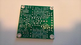
That works! I see the other side by scrolling down in the PDF. So that photo in post #1 actually IS the bottom. This will be a fun build. 🙂
Last edited:
Here is the BOM.
C2 R381 still need a little bit of tweaking to provide reliable start. With the current values sometimes I have to restart it to turn it on.
C2 R381 still need a little bit of tweaking to provide reliable start. With the current values sometimes I have to restart it to turn it on.
Here is the BOM.
Hey Sergey888! Your attachment ir link didn't make it through somehow. Thanks for putting that BOM together!
Best bang for b̶u̶c̶k̶ milliamp of the idle current - used two OPA2172 (OPA1688) in the output stage, leaving OPA1611 at the input.
Configured to G=-1. For G=-2 distortion scaled ~6dB (which is a good sign).
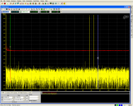
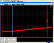
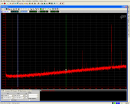
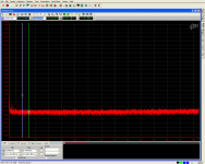
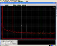
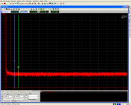
Output voltage was 2Vrms (+6dBVrms) in case of 20Hz, 1kHz, 10kHz and 20kHz test tones and 1Vrms + 1Vrms for the mix of 19.5kHz and 20.5kHz tones.
Load purelly active, 16.4Ohms.
Supply voltage is +/-6V
Have used a bit of a vector averaging in IMD test to reveal 18.5kHz and 21.5kHz components.
So, just briefly, for the 1kHz tone the second harmonic is ~-144dBc
for the 20kHz signal there are some higher order harmonics visible. 9th (180kHz) is on the level of ~-118dBc
Configured to G=-1. For G=-2 distortion scaled ~6dB (which is a good sign).
Output voltage was 2Vrms (+6dBVrms) in case of 20Hz, 1kHz, 10kHz and 20kHz test tones and 1Vrms + 1Vrms for the mix of 19.5kHz and 20.5kHz tones.
Load purelly active, 16.4Ohms.
Supply voltage is +/-6V
Have used a bit of a vector averaging in IMD test to reveal 18.5kHz and 21.5kHz components.
So, just briefly, for the 1kHz tone the second harmonic is ~-144dBc
for the 20kHz signal there are some higher order harmonics visible. 9th (180kHz) is on the level of ~-118dBc
Attachments
-
 opa211+2xOPA2172_1+1Vrms@16_4Ohm_19_5k+20_5k.PNG106.8 KB · Views: 729
 -
 opa211+2xOPA2172_2Vrms@16_4Ohm_20kHz.PNG82.5 KB · Views: 739
 -
 opa211+2xOPA2172_2Vrms@16_4Ohm_10kHz.PNG82.5 KB · Views: 738
 -
 opa211+2xOPA2172_2Vrms@16_4Ohm_1kHz.PNG73.2 KB · Views: 743
 -
 opa211+2xOPA2172_2Vrms@16_4Ohm_20Hz.PNG77.3 KB · Views: 758
Last edited:
"Best bang for a milliamp, episode 2" or "what it would look like if I substitute OPA1611 with OPA(2)172/(OPA1688)"
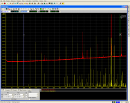
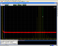
Conditions are exactly the same - output signal is at the same +6dBVrms. Used vector averaging during some measurements to get rid of interference.
20Hz and 1kHz spectra look quite clean, there is hardly a substantial difference, but it is obviously lover GBW opamp. It gives up much earlier - even 10kHz spectrum look quite contaminated with harmonics.
Is it really that bad? Perhaps no, since even tallest 7th harmonic for 20kHz signal is almost -109dBc and all these harmonics are far from audio frequency range. IMD spectrum has much wider skirt around the main tones, but it is still 119dB down.
Attachments
-
 opa172+2xOPA2172_2Vrms@16_4Ohm_20Hz.PNG78.3 KB · Views: 222
 -
 opa172+2xOPA2172_2Vrms@16_4Ohm_1kHz.PNG74.7 KB · Views: 187
 -
 opa172+2xOPA2172_2Vrms@16_4Ohm_10kHz.PNG92.4 KB · Views: 163
 -
 opa172+2xOPA2172_2Vrms@16_4Ohm_20kHz.PNG88.4 KB · Views: 184
 -
 opa172+2xOPA2172_1+1Vrms@16_4Ohm_19_5k+20_5k.PNG77.5 KB · Views: 178
I still have all my Crocodile parts sitting here in a box, ready to go! 😀 Too many fun projects and not enough time. I really should get this one soldered up. Looks like a good amp to try. 🙂
Apparently, the pcb delivery that took a few mounth wasn't the slowest part of your project 🙂
Lol! 🙂 Yep shipping was the fast part. 🙂
pm sent about board availability?
Didn't get any PMs, but I think I've got one or two PCBs left. Will check in the evening.
Alex - you will probably find that two of the coils Sergey888 used are available overseas but not through the distributors here. But you can order them directly off the coilcraft website, which is what I did. They were cheap too as I recall, like $2 each or so. 🙂
Serge,
Looking at the BOM and schematic at L301 and L302. its stating these are 4.7uh coils.
On the coilcraft site the LPD5030-103ME pn is for a 10uh coil, the pn for the 4.7 is: LPD5030V-472ME.
Also coilcraft states these are not recommended for new designs? and they point to there replacement: LPD5030V-472MR_
The original one they will not sell unless your an existing customer but the replacement they will...
Fyi
Alex
BTW, there was a minor update to the schematic/BOM. Will update it on some stage, but the quick summary:
R146, R147 - reducing to around 22-33Ohm would eliminate make power up (don't know how repeatable it is. Worked on my samples).
Both R64_Cx can be left non fitted - reduces parts count (they are the only ones 220Ohms 0603)
LT3467 can be raplaced with LMR64010 (or similar). They do not have a soft start pin, but they are drop-in compatible.
C66 - typo, read as 470p
- Home
- Amplifiers
- Headphone Systems
- "The Crocodile"