Wow, it was insanely quick, comparing to the last time.
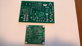
The crocodile does not have input/output/supply connectors on board, only 150mil screw terminals. This partly explains a difference.
Although now I think that molex 100mil "KK" would be a better choice. That would allow it to shrink it down to ~38x42mm.
The crocodile does not have input/output/supply connectors on board, only 150mil screw terminals. This partly explains a difference.
Although now I think that molex 100mil "KK" would be a better choice. That would allow it to shrink it down to ~38x42mm.
Attachments
Last edited:
Great, I am rounding up my stuff needed to start playing....I got a head magnifier, some solder paste, and flux pen, still need to get a hot air gun, debating which one to get without spending megabucks...print out the schematics, bom, study abit and order some parts!
The aim here is to have it be a nice headphone amp, not that I dont have several already!!
Thanks Sergey for the pcb, when I start I will post pix and progress.
Alex
The aim here is to have it be a nice headphone amp, not that I dont have several already!!
Thanks Sergey for the pcb, when I start I will post pix and progress.
Alex
Sergey,
Getting ready to ordering parts....
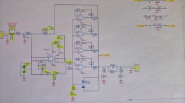
Need some help with schematic nomenclature:
NF = ? (assume not used in basic design?). (C53, C65, R58 as examples).
and with some caps, there is "SHORT" ??
(like C63)...is this meaning for the smallest height factor?
Thanks
Alex
Getting ready to ordering parts....
Need some help with schematic nomenclature:
NF = ? (assume not used in basic design?). (C53, C65, R58 as examples).
and with some caps, there is "SHORT" ??
(like C63)...is this meaning for the smallest height factor?
Thanks
Alex
NF = Not Fitted. Since it was an experiment, I added tons of passives everywhere where I though I may need it.
Short - I meant a wire link. I've never used it with an input cap - just have no source where I may need it. Added it "just in case". Depends on your needs, you can fit something suitable.
Short - I meant a wire link. I've never used it with an input cap - just have no source where I may need it. Added it "just in case". Depends on your needs, you can fit something suitable.
Thanks for that, another question:
Where are the L4, L5, L6, and L7 located? Looks like they are not on the pcb? What is the value? 1.5? Any part number?
Are they really needed? or is this dependant on how the board is mounted in a small enclosure etc?
Thanks
Alex
Where are the L4, L5, L6, and L7 located? Looks like they are not on the pcb? What is the value? 1.5? Any part number?
Are they really needed? or is this dependant on how the board is mounted in a small enclosure etc?
Thanks
Alex
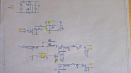
Well, I definitely need to update the schematic... sorry for the mess 🙂
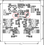
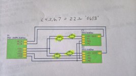
They were replaced with 1.5Ohm resistors. Does not have to be exact - can be anything from 1 to 2.something Ohms.
Location - see the pic (actually from the PDF with assy)
They were replaced with 1.5Ohm resistors. Does not have to be exact - can be anything from 1 to 2.something Ohms.
Location - see the pic (actually from the PDF with assy)
Attachments
No problem...thanks again for the data...
Once I get the two channels built, and the other circuits as required, I wanted to know how to tie them together...ha!
I will add some 1.5 ohm smd thin film resistors for these fourparts..gosh I looked at the layout a bunch of time and never saw these !!! Must be getting older!!!...
Alex
Once I get the two channels built, and the other circuits as required, I wanted to know how to tie them together...ha!
I will add some 1.5 ohm smd thin film resistors for these fourparts..gosh I looked at the layout a bunch of time and never saw these !!! Must be getting older!!!...
Alex
Does not have to be a thin film. You'll have 2.2Ohm 0603 from other places - just fit two in parallel.
Thanks again for the clarification....I don't have a stock of spare resistors etc...anymore, back when I worked at IBM and other companies we worked in labs with lots of electronics stuff that we could use, o'scopes, oscillators, vtvms etc...and lots of samples from TI and other companies, but those days are gone...have to order from Newark, farnell or digikey etc..so I need to get a pretty exact list to order and not have to keep ordering and pay the shipping etc...trying to get a BOM accurate to place the order in a few weeks.
Looking forward to building it, I just ordered a hot air gun, should be here next week, and have parts for AIM65's head amp that I will tackle first.
Thanks Again
Alex
Looking forward to building it, I just ordered a hot air gun, should be here next week, and have parts for AIM65's head amp that I will tackle first.
Thanks Again
Alex
It's not exactly what I meant. You'll need 2.2Ohm 0603 in the other part of the schematic anyway. I also used them instead of 0Ohm links where it is acceptable, to reduce number of lines in the BOM.
Just order a few extra - it gets cheaper with quantity 🙂
Just order a few extra - it gets cheaper with quantity 🙂
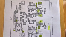
I took the time this morning to go over the parts layout on the pcb and identify what the NF's and SHORT's are, where they are located etc...So I can easily "see" whats not needed or not populated to make the crocodile work as a headphone amp.
I hope this helps anyone else that might want to "play: lol...
If there are any gross errors let me know Sergey.
I hope this helps anyone else that might want to "play: lol...
If there are any gross errors let me know Sergey.
Attachments
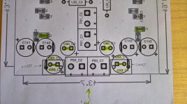
Spotted a thing - C58 is fitted, C56 is not. I guess you just accidentally mixed up those two designation on assembly drawing.
Also don't forget about those updates - http://www.diyaudio.com/forums/headphone-systems/270294-crocodile-4.html#post5014290
Also don't forget about those updates - http://www.diyaudio.com/forums/headphone-systems/270294-crocodile-4.html#post5014290
Thanks!! Made the change on my layout diagram.
Heres the updates to have in the same area of the thread:
BTW, there was a minor update to the schematic/BOM. Will update it on some stage, but the quick summary:
R146, R147 - reducing to around 22-33Ohm would eliminate make power up (don't know how repeatable it is. Worked on my samples).
Both R64_Cx can be left non fitted - reduces parts count (they are the only ones 220Ohms 0603)
LT3467 can be raplaced with LMR64010 (or similar). They do not have a soft start pin, but they are drop-in compatible.
C66 - typo, read as 470p
Alex
Note, I have a 12vac and a 18vac wall "wort: adapter from my O2's. I need to make sure the electrolytics are a higher voltage if I use the 18 vac one?
Last edited:
Neither LT3467 or LMR64010 will not work over 14-15Vdc. You'll need something rated lower, around 6Vac. 9Vac may be OK but depends on particular transformer regulation drop.
You can use a 5-12Vdc wall plug. Just keep in mind parasitic capacitance to mains, if it is an SMPS. Since you are not using balanced connection, it may significantly impact results.
You can use a 5-12Vdc wall plug. Just keep in mind parasitic capacitance to mains, if it is an SMPS. Since you are not using balanced connection, it may significantly impact results.
Last edited:
Great....
There are many dc wall worts at low cost:
https://www.amazon.com/iMBAPrice-Ad...8-3-fkmr0&keywords=9v+dc+power+adapter+adrino
Alex
There are many dc wall worts at low cost:
https://www.amazon.com/iMBAPrice-Ad...8-3-fkmr0&keywords=9v+dc+power+adapter+adrino
Alex
Those are smps, not the best choise, but can work for debugging.
In worst case you can add two big zeners in series with transformers you've got.
In worst case you can add two big zeners in series with transformers you've got.
Last edited:
- Home
- Amplifiers
- Headphone Systems
- "The Crocodile"