Speakers AB
Q274 collector base .527 V
Q272 collector base -.627V
This was a moment just before death of q272. Would thsee values indicate anything
One more thing.. amp works the same way with q272 blown.. same exact behavior as before. Speakers A on all the time
Q274 collector base .527 V
Q272 collector base -.627V
This was a moment just before death of q272. Would thsee values indicate anything
One more thing.. amp works the same way with q272 blown.. same exact behavior as before. Speakers A on all the time
Last edited:
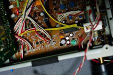
There seems to be a crack on the board around R194 and Q274.
Is the traces on the other side intact?
Is the traces on the other side intact?
It's a hair) my eyes brows have been over the amp for a very long time now..
Ordering replacement 2sa970BL x2 and 2sc2240bl x2 frombdenterprises. Bdent.com
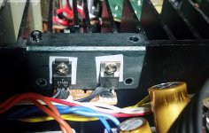
What about these transistors on radiators.. are they identical on your amp?
Ordering replacement 2sa970BL x2 and 2sc2240bl x2 frombdenterprises. Bdent.com
What about these transistors on radiators.. are they identical on your amp?
Attachments
Last edited:
Oh dear 🙁 New ones needed, and there should be plenty of generics that will fit the bill.
You said above 'negative meter lead to base'. The negative meter lead should go to chassis (ground) unless we are doing a specific check of voltage between or across two points.
You said above 'negative meter lead to base'. The negative meter lead should go to chassis (ground) unless we are doing a specific check of voltage between or across two points.
What about these transistors on radiators.. are they identical on your amp?
One of those isn't a transistor 😉 The 7812 is a 1 amp (or 0.5A as its an M variant) positive voltage regulator.
Ok. Once they arrive new transistors. Have an old cd olayer...maybe there are transistors there Thst will work.. will look into specs and post possible replacements.. 1 hour

Its not suitable. A 2N5401 would be a generic replacement (different pinout though) and a 2N5551 for the 2SC device.
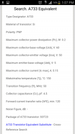
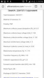
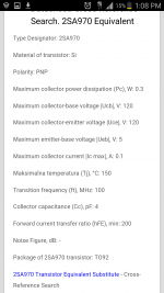
What about a1017.
Specs side by side. They seem to have same equivalent t092. But people said t092 is not the best substitute for a970
Only thing a1017 has very low ic max. Collector current .05 instead of .1
Specs side by side. They seem to have same equivalent t092. But people said t092 is not the best substitute for a970
Only thing a1017 has very low ic max. Collector current .05 instead of .1
Attachments
Last edited:
Ic could be an issue. It all depends on the relay current draw which is an unknown unless you measure it and see what it is. Its only two minutes of a job though.
My measurements (With the disclaimer that they might be wrong.).
Speaker A off
Q274
B-C 65V
B-E 0V
C-E 65V
Q272
B-C 60V
B-E 0V
C-E 5V
Speaker A on
Q274
B-C 0,53V
B-E 0,59V
C-E 0,07V
Q272
B-C 0,50V
B-E 0,75V
C-E 0,02V
Speaker A off
Q274
B-C 65V
B-E 0V
C-E 65V
Q272
B-C 60V
B-E 0V
C-E 5V
Speaker A on
Q274
B-C 0,53V
B-E 0,59V
C-E 0,07V
Q272
B-C 0,50V
B-E 0,75V
C-E 0,02V
My measurements (With the disclaimer that they might be wrong.).
Speaker A off
Q274
B-C 65V
B-E 0V
C-E 65V
Q272
B-C 60V
B-E 0V
C-E 5V
Speaker A on
Q274
B-C 0,53V
B-E 0,59V
C-E 0,07V
Q272
B-C 0,50V
B-E 0,75V
C-E 0,02V
Wow thanks a lot. I did not measure correctly. Need to measure the proper way. With black or negative multimeter terminal touching the chasis. I hope I read it right. That's what Mooly mentioned.
But if u measured voltage same way I did I am sure these will be very helpful once I replace blown q272
As for transistor substitutes, for 2SC2240/2SA970 I've used KSC1845/KSA992 before, but never as relay drivers.
If you remove Q272 and Q274, the relay shouldn't engage any more.
If it still does, there must be a solder bridge along the way or some kind of modification.
If you remove Q272 and Q274, the relay shouldn't engage any more.
If it still does, there must be a solder bridge along the way or some kind of modification.
Wow thanks a lot. I did not measure correctly. Need to measure the proper way. With black or negative multimeter terminal touching the chasis. I hope I read it right. That's what Mooly mentioned.
But if u measured voltage same way I did I am sure these will be very helpful once I replace blown q272
I measured as you did (with the paranoid caution of not doing it directly at the transistor legs), but swapped red and black probe.
Interesting. So if I unsolder both q272, q274. Then when switching speaker options A,b,ab, off, remote.
I should Not Hear that Main board relay click right? And non of the speakers will produce any sound?
I should Not Hear that Main board relay click right? And non of the speakers will produce any sound?
Just pull Q272. If you stick your meter on a DC current range and connect it across C and E of Q272 then the relay will operate and you will be able to measure the current.
Just pull Q272. If you stick your meter on a DC current range and connect it across C and E of Q272 then the relay will operate and you will be able to measure the current.
30mA
PS
Don't forget to put it back to voltage measuring afterwards.
DS
Unsoldered q272 q274. Same behavior. Left channel a little quieter..I'll take few pics of the board. But don't see anything obvious.. like some one worked on it before.
Maim board relay stil clicks when switching between options
Maim board relay stil clicks when switching between options
Attachments


Last edited:
Only thing there is a pair of 2 pin jumpers That don't have anything attached to them. .what are these for?
Here is a pic of one. It's white housing and 2 pins. There are 2 of them. One on each channel. Right by output transistors of left and right channels. Can be seen without removing much
Here is a pic of one. It's white housing and 2 pins. There are 2 of them. One on each channel. Right by output transistors of left and right channels. Can be seen without removing much
Attachments

Those could be test points for setting bias current... highly likely given their location.
With Q272/274 removed then the relay that they control should not operate. You need to confirm that by observation and making sure that the relay does not now have any voltage across the coil.
You still have the other pair of transistors and the relay that they control.
If you are not sure what goes where then you need to trace the speaker feed that isn't behaving correctly back to the relay. That is the only sure way you will identify it. You can then see if that relay is behaving or not. When a relay opens the circuit is broken and the speaker should go silent.
- Status
- Not open for further replies.
- Home
- Amplifiers
- Pass Labs
- Nakamichi stuck in speakers A all the time.