So I believe this deserves a separate thread. I did complete recap of nakamichi ta-4a.
But initial problem is still present.
Basically speakers A are always on. If u switch on receiver speakers A, speakers b, speakers a+b , speakers off, speakers remote. Speakers A always play regardless of the switch position.
When I put that switch to "speakers remote " and then switch between various options on remote speakers A stil ll stay play all the time. Display shows correct selection.
I desoldered one dc relay on the main board, removed top cover and sprayed deoxit f5 fader inside. Moved relay in and out with screw driver. But That did not help.
There is one more relay near transformer, power supply board. Right where power cable is soldered. Havent done anything with This relay
Another thing I noticed. When receivers selector is set on "remote" and I use remote control to switch I hear main board relay click when doing speAkers" off" to speakers "B" switch, off to speakers AB. But when doing speakers off to speakers A I don't hear any clicks..
Last edited:
Another thing I noticed this ta-4a does not control woofers well..when I play some moderately bass heavy tracks woofers move very slowly. Kind of float. Whe. Same tracks played by yamaha mx1 or ta-3a woofer spring back and forth pretty fast. I did turn off subsonic filter on all amps just to make things equal.
What could cause this behavior. DC curgent leakage? How can I monitor this? Oscilloscope?
What could cause this behavior. DC curgent leakage? How can I monitor this? Oscilloscope?
I'd suspect that a transistor in th relay circuit isn't working as it should, will take a look at the chematics when I'm home from work.
Might be as simple as a bad solder.
Might be as simple as a bad solder.
Thanks. I think I saw your posts in similar thread about ta-4a. U were helping a guy from Argentina. I am away from the amp for a day or two.. but will definitely take pics of anything u needI'd suspect that a transistor in th relay circuit isn't working as it should, will take a look at the chematics when I'm home from work.
Might be as simple as a bad solder.
In your 'capacitor' recap thread you mentioned:
Is the sound you hear coming from the speakers ? or from within the amplifier. If the later then its normal. If coming from the speakers then its not normal.
Also while waiting for relay to click you can hear very low volume music. And then after relay clicks it's normal sound.
Is the sound you hear coming from the speakers ? or from within the amplifier. If the later then its normal. If coming from the speakers then its not normal.
Yes sound I am talking about Is from speakersIn your 'capacitor' recap thread you mentioned:
Is the sound you hear coming from the speakers ? or from within the amplifier. If the later then its normal. If coming from the speakers then its not normal.
So when I have speakers plugged into speakers A. I hear this low volume music in that 2-3 second window till dc relay clicks
When speakers are plugged into speaker B I don't hear music in the same time frame. (Power button press--dc relay click )
Sound from the speakers when the speaker relay is supposed to be open is very odd.
Can you be certain the relay is open during this time ? I haven't seen the circuit so I'm just thinking of possibilities but if the relay were in fact closed all the time and there was also some 'soft muting' elsewhere in the amp (such as the input to the power amp) then that could give the symptoms you describe.
First check has to be to determine if the relay is closing at power on (when it should not).
This is from the other thread. I think this is what u wanted me to test.
Cleaned speaker selectors. They are twist type selectors.. also speakers A are on even before DC relay clicks.. I tend to think it's man made probmem. Ebay purchase..I may be wrong of course.
I'll work on getting circuits.
It seems like it's a power amp section problem.
I tried testing speaker selector connection. Looks like relay works. When receiver is off there are no connections between pins. No beep sound from multimeter.
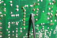
So relay looks like this. I did connection test using multimeter connection test "beep" option.
. . .
. . .
Last 2 vertical dots is DC feed To actuate.
First 2 vertical dots are speakers B I guess. These two are connected when b or a+b are selected.
The middle vertical pair is speaker A I think. It's always on. As soon as u hit power relay connects speakers A. And when u turn off the amp connection is still there for 2-3 seconds or till capacitors discharge.
Speakers b pins actually wait till relay in power supply section clicks.. and then u get a connection between speaker B pins.
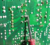
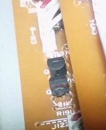
Just quick picks of speaker relay with screw driver showing the pins.
Oh also I checked dc voltage during switching a,b a+b option. When I click on remote speaker B there is 22v dc in relay. When speakers a are chosen current is 0v.
Cleaned speaker selectors. They are twist type selectors.. also speakers A are on even before DC relay clicks.. I tend to think it's man made probmem. Ebay purchase..I may be wrong of course.
I'll work on getting circuits.
It seems like it's a power amp section problem.
I tried testing speaker selector connection. Looks like relay works. When receiver is off there are no connections between pins. No beep sound from multimeter.
So relay looks like this. I did connection test using multimeter connection test "beep" option.
. . .
. . .
Last 2 vertical dots is DC feed To actuate.
First 2 vertical dots are speakers B I guess. These two are connected when b or a+b are selected.
The middle vertical pair is speaker A I think. It's always on. As soon as u hit power relay connects speakers A. And when u turn off the amp connection is still there for 2-3 seconds or till capacitors discharge.
Speakers b pins actually wait till relay in power supply section clicks.. and then u get a connection between speaker B pins.
Just quick picks of speaker relay with screw driver showing the pins.
Oh also I checked dc voltage during switching a,b a+b option. When I click on remote speaker B there is 22v dc in relay. When speakers a are chosen current is 0v.
Attachments
Last edited:
So it sounds as if the relay is active from the moment you turn the amp on.
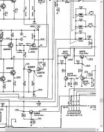
Seeing the circuit of the relays and their drivers would make it all much clearer to diagnose.
Seeing the circuit of the relays and their drivers would make it all much clearer to diagnose.
So it sounds as if the relay is active from the moment you turn the amp on.
Seeing the circuit of the relays and their drivers would make it all much clearer to diagnose.
I agree) but I am not home for few days. Did not notice cracked transistors. But I've heard small transistors can fail without visible cracks
Yes speakers A are connected the moment power button is pressed
Its dead easy to fault find something like this. Just monitor the relay coil voltage (measure across the coil) and see what happens. Typically one end of the coil will be switched via a transistor.
Again, the circuit diagram will reveal all 🙂
Again, the circuit diagram will reveal all 🙂
Just like a map. The bit you want is on the edge of the page. Must admit its a complex receiver but the relay drive is conventional. What controls the relay drivers isn't though.
The relays activate when the base of the NPN drivers goes high (to 0.6 volts). So that is the first thing to measure. If either of those are high at power on then the appropriate relay/s will activate.
The relays activate when the base of the NPN drivers goes high (to 0.6 volts). So that is the first thing to measure. If either of those are high at power on then the appropriate relay/s will activate.
Attachments
Ok found q274
When speaker a+b collector /base voltage is .52v. Emitter/base is .072v
Speaker B.
Collector base voltage is 9v
Emitter base is 55v
Speaker A
Collector base is .52v
Emitter base is .072v
Speakers off
Collector base is 9v
Emitter base 55v
Speakers remote
Collector base 12v
Emitter base is 55v
I was thinking That maybe it's good to follow signal patg.. right after power button press. Maybe something in power supply board.
Last edited:
The emitter of Q274 should be ground.
Where does the 55 volts come from ? You cannot get more than around 0.8 volts ACROSS a forward biased base/emitter junction.
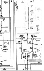
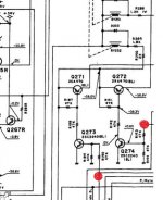
Its easy 🙂 look at Q272 and Q274 as an example. Do you see the two 47k resistors at the right of Q274. When the relay is supposed to be OFF then there will be zero volts on that upper 47k (R193 I think it is). The collector of Q274 will be high at nearly 60 volts. Q272 will be OFF and the relay not activated.
When the voltage on the top end of R193 goes high (probably 5 volts) then the base of Q274 will show around 0.6 volts. Q274 will now be ON and the collector voltage will be near zero. That will turn ON Q272 and the relay will operate. Under those conditions there should be around 0.6 volts ACROSS R191 (the 47k across B and E of Q272)
The other relay driver works exactly the same.
Bottom line is that when the two points marked in red are high (5V) the appropriate relay should be ON. When they are low (0V) the relay should be off.
Where does the 55 volts come from ? You cannot get more than around 0.8 volts ACROSS a forward biased base/emitter junction.
Its easy 🙂 look at Q272 and Q274 as an example. Do you see the two 47k resistors at the right of Q274. When the relay is supposed to be OFF then there will be zero volts on that upper 47k (R193 I think it is). The collector of Q274 will be high at nearly 60 volts. Q272 will be OFF and the relay not activated.
When the voltage on the top end of R193 goes high (probably 5 volts) then the base of Q274 will show around 0.6 volts. Q274 will now be ON and the collector voltage will be near zero. That will turn ON Q272 and the relay will operate. Under those conditions there should be around 0.6 volts ACROSS R191 (the 47k across B and E of Q272)
The other relay driver works exactly the same.
Bottom line is that when the two points marked in red are high (5V) the appropriate relay should be ON. When they are low (0V) the relay should be off.
Attachments
You wrote that "Speaker A" indicator led on the display works according to speaker selector settings, aka it's not always on, only when it's supposed to.
Then we can assume that the remote selector circuit and speaker switch is working as intended.
That leaves Q272 and/or Q274 problem to be the most likely culprit.
I measured resistance between emitter and collector on those.
(Maybe not a conclusive way to determine if there is a short between E and C.)
(The unit was turned off when I did this.)
Q274 50-100K Ohm
Q272 8K Ohm
If Q272 is shorted, it might cause a unbalance between the positive and negative 59V rails, the relay circuit use the positive 59V rail for the relays.
This could cause a big DC-offset that affects Bass reproduction.
(I'm probably on limb here, since I'm just a happy amateur ;-) )
I'll take voltage measures on Q272/274 on my unit for reference.
Last edited:
(I'm probably on limb here, since I'm just a happy amateur ;-) )
Nothing wrong with that 🙂
You will find that if Q272 were shorted then the only symptom would be that the relays switched via that transistor would be on all the time.
Resistance readings taken in circuit don't really mean much I'm afraid because they are affected by so many outside variables. Any slight voltage residual from charged caps will affect most DVM resistance readings, so to the meter lead polarity and also the test voltage the meter applies. Only if the transistor had a near short would it be OK to act on the readings.
Will check q272.
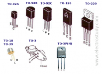
They don't look cracked.
And one more thing.. I used emitter collector base scheme as shown on transistor 2nd from the left ..maybe q272, q274 are different. Basically collector is the terminal closest to the edge of the board. Base is the middle and emitter is farther from the edge
They don't look cracked.
And one more thing.. I used emitter collector base scheme as shown on transistor 2nd from the left ..maybe q272, q274 are different. Basically collector is the terminal closest to the edge of the board. Base is the middle and emitter is farther from the edge
Attachments
Ok updated values. Negative multI meter is always at the base. Measuring collector and emitter with positive multimeter terminal.
Speakers AB
Q274 collector base .527 V
Q272 collector base -.627V (I think I fried something shorted collector and base by accident. Heard a moderate bang /short.. now voltage is .02v)
Q274 emitter base -.055V
Q272 emitter base .036V
speaker B
Q274 collector base -11.8 V
Q272 collector base .04V
Q274 emitter base -54V
Q272 emitter base .04V
Speaker A
Q274 collector base .52v
Q272 collector base .016V
Q274 emitter base -.055V
Q272 emitter base .018V
Speakers off
Q274 collector base -12.4V
Q272 collector base .018V
Q274 emitter base -55.3v
Q272 emitter base .016v
Speakers remote
Q274 collector base -12.4V
Q272 collector base .018V
Q274 emitter base -54.7v
Q272 emitter base .017v
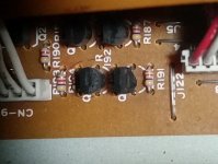
****.. just looked at q272..it blew. Half of it blew off.
It's the one I shorted by accident so all those measurements. Are sort of useless. Need to replace Q272 and Q274 I guess
It's the one I shorted by accident so all those measurements. Are sort of useless. Need to replace Q272 and Q274 I guess
Attachments
Last edited:
- Status
- Not open for further replies.
- Home
- Amplifiers
- Pass Labs
- Nakamichi stuck in speakers A all the time.