A couple of random thoughts.
Sweep Tubes often like to see a screen supply of around 1/2 the anode voltage. That is a problem when you go UL connection unless you have a specialist transformer with separate UL winding rather than simple taps on the primary.
The UL feedback voltage is from screen to cathode so when you add in cathode feedback it adds to the UL feedback voltage.
Cheers,
Ian
roger all that, of course. In my scheme, the G2s of the PAs are at 120V regulated, measured to ground. Not in a UL circuit configuration at all, fixed 120V (which may be adjusted in value pending building and testing).
The effective UL (just like with my use of the term Schade style feedback, UL is being used here not to justify anything but simply to describe) operation is as follows: Because I am employing CFB which will apply about 10% of the swing within the transformer primary for the corresponding plate, the cathode voltage is rising as the plate voltage is decreasing (voltage across the primary plate winding is increasing). This causes the effective G2 to cathode voltage to decrease proportionally just as in UL operation. The G2 maximum voltage is being strictly respected (speaking statically). The reverse operation takes place as the corresponding tube is being driven toward cutoff, the cathode voltage is actually going below ground hence increasing the effective G2 to cathode voltage proportionally (by the CFB factor), same exact effect as when operating in traditional UL connection.
If I don't like what I get with this UL side effect, all that needs to be done is connect a big enough cap between G2 and cathode and the G2-cathode voltage becomes steady and UL operation goes away.
Love all the other inputs and comments, I am learning a lot from them. If I were after more power, I sure would dive deeply into the dual drive schemes!
Miles, thanks a lot for the 6HJ5 set of curves!
Rene
Hmmm, minor correction,
------------------------------------------------------------------------------
"I wonder though, why Edcor positions them as 15W transformers, if they are capable of 4.5W only down to 110 Hz, then saturate?"
How much DC current are you putting through that SE OT? The GXSE-15 I measured once did just hit hard saturation at the 15 Watt level. No room to spare. SE OTs should be de-rated for max power at the max permeability point, or just above, I think. So about 1/2 the Watt ratings given. Those who rave about SE OT performance don't have any idea how badly those things actually perform. 🙄
In fact, in order to be able to handle the DC bias on the core, an airgap is used,which goes in the denominator of the inductance calculation and reduces the inductance quite quickly. As far as the dynamics go, the SE transformer, due to the absence of a bipolar current swing, only less than half the available BH loop can be used. The BH curve is also extremely laid on its side, reducing the effective permeability, further reducing inductance. In fact, is this laying down which produces the unit's ability to operate with a DC bias. Instead of the idle point represented by being close to the origin, the q point is halfway up one of the quadrants (depending on polarity) and can never go into the opposing quadrant, thereby cutting the effective range to plus and minus a half of a half.
This effect was mitigated a bit by the old tube radios which used a "hum bucking" tap, where a small amount of current was flowing from that tap out in the opposite direction as the current to the plate, partially offsetting that current. Just a little nostalgic bit of info. I have several RCA radios which used that trick, all with a 6V6 output tube. Certainly reduces the hum. I am more impressed by the RF portion of those sets than their audio. But they sure do reduce the hum from the PA. Very little when the volume is turned all the way down and ear close to the speaker.
But I fully agree, no way am I going to design/build a SE amp and expect high quality of output. Other than as output stages of comm sets where audio is not important but circuit simplicity makes sense, SE has no place in my line of thinking.
Rene
My experience has been that UL (negative voltage feedback to the screen grid) is an inferior form of feedback to voltage feedback to the control grid. If you take a UL output stage (or effective UL/CFB combo) and compare it to an output stage with only series or parallel applied voltage feedback to the control grid, I think you will find that for an equal closed-loop gain comparison the control grid correction (so-called Schade) will have lower distortion.
This makes intuitive sense as well. We shouldn't expect to take an error that originated in one electrode and apply a correction to some other electrode and have that work best. It is best to correct the error in the electrode in which it originated, and exclusively there if possible. In reality, we make engineering compromises to make a reasonably simple circuit.
The appeal of UL is in its simplicity. I did build an amp once with a very simple form of parallel-applied voltage feedback using a p-channel fet follower. It requires a couple of negative rails but is otherwise very simple. Feedback ratios up to ~25% are feasible in this configuration. I have this amp back now and will be performing and posting some extensive measurements in the next couple of months in this thread: http://www.diyaudio.com/forums/tubes-valves/248376-amp-kt88-push-pull-shunt-feedback-output-via-p-channel-fet.html
Stay tuned if that approach looks interesting to you.
Cool, looking forward to the published data! Your use of the MOSFETs isolates the feedback current from the drivers. In my case, the drivers can handle the current.
If you go back to my original post with the circuit description, "Schade" style feedback is used with the PAs. The "UL effect" is simply a byproduct of CFB and can easily be eliminated with caps.
Please publish!
Rene
If you go back to my original post with the circuit description, "Schade" style feedback is used with the PAs. The "UL effect" is simply a byproduct of CFB and can easily be eliminated with caps.
Please publish!
Rene
Cool, looking forward to the published data! Your use of the MOSFETs isolates the feedback current from the drivers. In my case, the drivers can handle the current.
If you go back to my original post with the circuit description, "Schade" style feedback is used with the PAs. The "UL effect" is simply a byproduct of CFB and can easily be eliminated with caps.
Please publish!
Rene
Oh, I understand what you are saying with the "UL effect" and all that. I'm not suggesting you take it away, either. I'm just pointing out that if it is easy to go one way or the other, I know what I'd choose.
As far as your approach goes, I think it will perform well. I've always had (maybe unfounded) concerns with the linearity of pentodes as V-to-I converters. That's why I did V-to-I conversion through a resistor driven by voltage source (the fet). Maybe pentodes are better than I think, especially if they have some degeneration. Too many threads out there to follow them all...
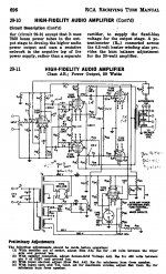
The RCA 50 Watt (tube handbook) amplifier does a neat trick to linearize the pentode drivers. N Fdbk to the 6CB6 cathodes makes the degeneration resistors look much bigger.
-----
"We shouldn't expect to take an error that originated in one electrode and apply a correction to some other electrode and have that work best."
Grid2 generally works fairly close to a 3/2 power law for V to I. (can be a little less, like 1.3 or 1.4 in aligned wire grid tubes), while grid1 works more like 2.0 power law (over a good central part of the use-able range at least). So running N Fdbk to grid2 will leave some 2nd Harmonic dist. in (from the 0.5 discrepancy), like a triode. But becoming 3rd H in P-P though.
Would be interesting to turn the tables. Drive grid2 and put N Fdbk back to grid1. This might give one "anti-triode" like distortion (-0.5 discrepancy), which might work well opposite a conventional UL Fdbk on the other P-P side to sum to a SE triode characteristic.
--
Attachments
Last edited:
You don't know what you're discussing.
Perhaps you are right and me wrong, but in any case you don't need to be too agresive.
The RCA 50 Watt (tube handbook) amplifier does a neat trick to linearize the pentode drivers. N Fdbk to the 6CB6 cathodes makes the degeneration resistors look much bigger.
I had seen that schematic before but never had made the connection that that's what they were doing there. Thanks for pointing that out.
TV tubes versus Audio tubes
The TV tubes were designed for maximum economic effectiveness, so the grid1 gm is pushed higher than the older audio tubes I think. That causes some additional 2nd and 3rd H distortion (not so obvious in the plate curves unless you analyze the vertical spacing variation). So you do need some additional N Fdbk to correct that typically. (which the extra grid1 gm allows for) Going with grid 2 (TV tube) drive, however, completely reverses the tables, since it is lower gm than the grid 1 in audio tubes. And the aligned grids can reduce the grid2 power law below 1.5. (I measured 1.3 power law in a 6LQ6 once, almost linear. Higher plate current reduces the power law too.)
The subtle issue in most any of the pentode tubes is the slow curvature (from screen grid current) of the plate curves throughout the plate V range. I think this is what is responsible for many pentodes having an optimum load impedance (OT primary) (3rd harmonic typically picks up above the optimum Z).
The few pentode tubes (or Mosfets) that do have fairly straight plate curves should be able to benefit from higher load Z than usual, like triodes do. However, the OT BW suffers from endlessly increasing the primary Z, and TV tubes have plenty of current drive already to drive low Z loads anyway. (which you already paid for with the high heater current!)
21/6LG6 is an example. Almost like a Mosfet in a bottle. Almost interchangeable with the 6HJ5 too.
https://frank.pocnet.net/sheets/123/6/6LG6.pdf
--
Last edited:
How much DC current are you putting through that SE OT? The GXSE-15 I measured once did just hit hard saturation at the 15 Watt level. No room to spare. SE OTs should be de-rated for max power at the max permeability point, or just above, I think. So about 1/2 the Watt ratings given. Those who rave about SE OT performance don't have any idea how badly those things actually perform. 🙄
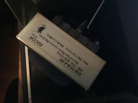
No, GXSE are fine. I mean this ones.
Attachments
The RCA 50 Watt (tube handbook) amplifier does a neat trick to linearize the pentode drivers. N Fdbk to the 6CB6 cathodes makes the degeneration resistors look much bigger.
It is unfair! 😡 It is almost my Pyramid amp, designed independently from them! 😡
However, no feedback to cathodes in mine, but I use servo from the tail to screen grid of the 1'st pentode! 😀
And I use a LTP directly coupled to Concertina.
Last edited:
"It is unfair! It is almost my Pyramid amp, designed independently from them! "
Great minds think alike.....
-----------------
"No, GXSE are fine. I mean this ones."
OH, XSE!
1/2 the price, 1/2 the freq. response. Seems fair.
Like 1/2 a car for 50%. 2 wheels.
Great minds think alike.....
-----------------
"No, GXSE are fine. I mean this ones."
OH, XSE!
1/2 the price, 1/2 the freq. response. Seems fair.
Like 1/2 a car for 50%. 2 wheels.
Last edited:
A LTP produce allready two phases, why a concertina 😕It is unfair! 😡 It is almost my Pyramid amp, designed independently from them! 😡
However, no feedback to cathodes in mine, but I use servo from the tail to screen grid of the 1'st pentode! 😀
And I use a LTP directly coupled to Concertina.
Mona
Motorcycle with 4 wheels?
Hah.
Gives me an idea. Suppose you have two SE triode amplifiers. But one has the input signal inverted, but also the output OT terminals are reversed to get the same phase out again. Each has its own speaker on opposite sides of wall. Nominally, they are both putting out the same sound, and should reinforce at the center. But each has distinctly different even harmonic distortion. In the center they should sound like P-P. But to each side there would be a distinct difference. Would sound stage or something be enhanced?
Last edited:
A LTP produce allready two phases, why a concertina 😕
Mona
Pentode LTP provides some gain and needed for GU-50 swing, being loaded on a parallel feedback from anodes of output tubes. It has to be symmetric for that, and fed by symmetric input.
Attachments

Last edited:
Motorcycle with 4 wheels?
Hah.
Gives me an idea. Suppose you have two SE triode amplifiers. But one has the input signal inverted, but also the output OT terminals are reversed to get the same phase out again. Each has its own speaker on opposite sides of wall. Nominally, they are both putting out the same sound, and should reinforce at the center. But each has distinctly different even harmonic distortion. In the center they should sound like P-P. But to each side there would be a distinct difference. Would sound stage or something be enhanced?
Nikola AKA Azazello insists that single ended distortions enhance sound stage. But I can't stand intermodulation... It sounds nasty to me. Tastes are different! I prefer amps and speakers to disappear.
Ah yes, a concertina FOLLOWED by a (not so)LTP 😎Pentode LTP provides some gain and needed for GU-50 swing, being loaded on a parallel feedback from anodes of output tubes. It has to be symmetric for that, and fed by symmetric input.
I got the idea you mend the other way around

Mona
Ah yes, a concertina FOLLOWED by a (not so)LTP 😎
I got the idea you mend the other way around
In respect to the load on a parallel feedback it is Long Enough TP.
For DC feedback the tail is usefull, it's only a common cathode resistor.In respect to the load on a parallel feedback it is Long Enough TP.
And now hoping that V2 and V3 devide the tail current equally.
Mona
Good Morning, Good Folks:
OK, reality has just set in, I will not be able to properly finish the schematic, nor do the really comprehensive circuit analysis I promised.
So instead, the work in process schematic is attached with a few notes so Y'all can picture what is missing.
What is missing:
There y'all have it. Please go for it.
Rene
OK, reality has just set in, I will not be able to properly finish the schematic, nor do the really comprehensive circuit analysis I promised.
So instead, the work in process schematic is attached with a few notes so Y'all can picture what is missing.
What is missing:
- I intend to have a bandpass input network so input signals are limited to the classic 20-20KHz range, before even being applied to the input amp grid.
- No frequency response shaping networks are currently included but I'm sure will be necessary. This includes finding the resonant frequency of the transformer and properly compensating for this. Since measurement must be made first, nothing is now determined.
- The LPTs tail current sink will be set to 8mA, need to transfer values from my calculations sheet to the schematic.
- The OPT is a custom. Still mulling over if I will build myself or have it done. Any suggestions for a custom winder who does not believe their stuff is somehow gold plated? 🙂
- Similarly, I have sent an email to Temple steel (for the laminations), Bahrs Die (for the end bells) and Foremost Plastic (for the bobbins). So far, only Bahrs has responded. Anyone know of a source of low quantities steel and bobbin?
- The circuit topology lends itself to some flexibility. For instance, there is room for PA plate to driver cathode feedback similar to the RCA 50W scheme. Especially if I turn the 1.1K to an actual active sink, a lot of DC offset (or more correctly put, disturbance of the driver's bias) that would otherwise appear will be handled by an active sink, though the idle plate current is thus reduced by the same amount as the feedback increases the current to the degeneration resistor.
- The funky resistors, R11 and 12, are there to improve balance of the input stage, and provide dynamic improvement of CMR.
- Initial calculations do not suggest the need for any balancing adjustment pots, due to the generous cathode degeneration. But I'm ready to add these if testing shows their need.
- No bias adjust is being shown but will be needed. The scheme to monitor both the bias and the bias balance is also not shown.
- G2 voltages are subject to adjustment, these are theoretical values. I don't see the +B (360V) changing, though.
There y'all have it. Please go for it.
Rene
Attachments
- Status
- Not open for further replies.
- Home
- Amplifiers
- Tubes / Valves
- 60W with CFB, using Sweep Tube, Full Differential