Indeed, George and Miles. About a couple of years ago when I first embarked on this quest, after posting the concept (which was a bit different than the current one but in the same ballpark), George posted both an endorsement on the idea of using sweep tubes, and referred to several predecessor threads which fully validated the use of sweep tubes, from the cost, the ruggedness and the performance. He also recommended that I look at G2 drive, which I did. Only reason to not go that way (if the G1/Plate family of curves look good, the G2/Plate curves are spectacular!), is I really don't need more than 20W so 60 is for margin, and did not want to complicate things by needing power to drive G2.
But I am sold on sweep tubes. Most bang for the buck, as long as one is not driven by guruship and unfounded opinions.
As to being good for switching, so is a 6V6, KT88, 6L6/807, etc. You can run any of these in a Class C power amplifier at high frequencies (essentially switching duty, if you are running at, say, 10MHz, the whole drive event is over in nanosecods) and yet all are thought as being great audio tubes. Running an RF PA in class C is akin to resonant SMPS designs that I and many others have implemented with MOSFETs. Again I say, they are great in audio service. Tubes are just fast, period. Truly switching tubes are very special and usually gas filled and behave more like an SCR. Otherwise, except for some very special designs and those with remote cutoff G1s, they are pretty good across the board for linearity.
Miles, I wonder if sweep tubes and audio were deliberately not correlated by the manufacturers possibly to protect the audio tubes from price pressures? I'm not usually a cynic but, catches my eye. Or it could simply be they were so focused on the sweep application that they never extrapolated to the audio (or RF) field. My old Tempo One uses sweep tubes for the PA, while Mac used sweep tubes for some of their audio amps.
Wavebourn, I got it and understand it, very cool and simple, thanks. If I have a heater winding available, I'll consider it. Likely, I won't. I can always turn the series MOSFET into a current limit circuit set to a little over the running (hot) heater current. This will force a soft start which will be great for the heaters and allow the SMPS to start into a load which is not a negative resistance. The PS design is not finalized so all inputs will go onto the story board for consideration.
Thanks, Y'all
Rene
I think what scared designers off from TV Sweep tubes were the "kinks" in the plate curves near the knees. Audio tubes promoted the "kinkless" feature. But these are really out of the way for a typical load line, as long as the load is not grossly reactive (an elliptical load line).
Grid 2 drive gets rid of the "kinks" by the way. (see below) The low grid 2 voltages for the "Sweep" tubes helps make g2 drive fairly practical. With a g1/g2 Mu of only 3 or 4, it just takes 3 or 4 X the drive swing of grid 1.
The recent "discovery" or "re-discovery" of combined grid2 and grid1 drive (Twin [or Crazy] drive) now fixes the voltage swing issue further. Only about 2X that of grid 1 drive. (or about 30% less than grid 2 drive) With even further increased linearity. Efficiency should also be quite good too, since little conduction overlap is needed with either g2 or Twin drives to smooth out crossover distortion in P-P.
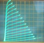
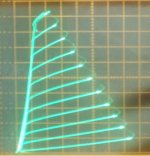
Some curves for the 40KG6/PL509 shown below in various modes:
(any Sweep tube seems to work quite well in Twin drive, even $1 ones)
All are curve traced at 50 mA/div Vert. and 50V/div Horiz. (except #5, is 10 mA/div Vert.)
1) PL509 normal g1 drive, -1.5V steps on g1, 78V on g2, top curve is 0V on g1
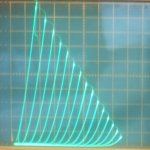
2) PL509 g2 drive, +5.5V steps on g2, g1 at 0V, bottom curve is 0V on g2
3) PL509 triode mode, -7.5V steps on g1, top curve is 0V on g1
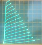
4) PL509 Twin/Crazy drive (g2 and g1 with resistors), +3.5 V steps on g2, Rg2g1 = 888 Ohm, Rg1k = 2770 Ohm, bottom curve is 0V on g2 (and g1)
5) $1 frame grid tube in Twin drive
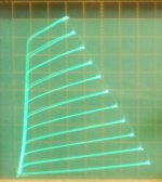
6) 6HJ5 in Twin drive
7) 1$ Sweep tube in Twin drive
Grid 2 drive gets rid of the "kinks" by the way. (see below) The low grid 2 voltages for the "Sweep" tubes helps make g2 drive fairly practical. With a g1/g2 Mu of only 3 or 4, it just takes 3 or 4 X the drive swing of grid 1.
The recent "discovery" or "re-discovery" of combined grid2 and grid1 drive (Twin [or Crazy] drive) now fixes the voltage swing issue further. Only about 2X that of grid 1 drive. (or about 30% less than grid 2 drive) With even further increased linearity. Efficiency should also be quite good too, since little conduction overlap is needed with either g2 or Twin drives to smooth out crossover distortion in P-P.
Some curves for the 40KG6/PL509 shown below in various modes:
(any Sweep tube seems to work quite well in Twin drive, even $1 ones)
All are curve traced at 50 mA/div Vert. and 50V/div Horiz. (except #5, is 10 mA/div Vert.)
1) PL509 normal g1 drive, -1.5V steps on g1, 78V on g2, top curve is 0V on g1
2) PL509 g2 drive, +5.5V steps on g2, g1 at 0V, bottom curve is 0V on g2
3) PL509 triode mode, -7.5V steps on g1, top curve is 0V on g1
4) PL509 Twin/Crazy drive (g2 and g1 with resistors), +3.5 V steps on g2, Rg2g1 = 888 Ohm, Rg1k = 2770 Ohm, bottom curve is 0V on g2 (and g1)
5) $1 frame grid tube in Twin drive
6) 6HJ5 in Twin drive
7) 1$ Sweep tube in Twin drive
Attachments
-
 rsz_40kg6_g1_1p5vst_78vg2_50_50.jpg82.9 KB · Views: 320
 -
 rsz_40kg6_g2_5p5vst_50_50.jpg76 KB · Views: 329
 -
 rsz_40kg6_triode_7p5vst_50_50.jpg74.6 KB · Views: 322
 -
 rsz_40kg6_twin_3p5vst_888rg2g1_2770rg1k_50_50.jpg74.9 KB · Views: 331
 -
 Crazy_TFH.JPG172.3 KB · Views: 292
 -
 rsz_6hj5_special_7Vs_75V.jpg73.1 KB · Views: 59
 -
 rsz_21hb5a_special_7vs_78v.jpg64.7 KB · Views: 58
Last edited:
Now I lust for a curve tracer!
Great post, thanks! Gorgeous curves. Clearly demonstrates the virtues of G2 drive but also shows the sweep tube as being just as capable as dedicated audio tubes.
As for kinks, the venerable KT88 has kinks but, as you point out, way out of the way of any normal dynamic operating point, at both low plate voltage and current, which by definition cannot be when swinging a normal load line.
Now back to the tracer: let's see, if I add up how much I can get for the dog and the bicycles, how many lemonades my daughters will have to sell... hmm!
Rene
Those were traced on a modified Tek 576 curve tracer (normally for SS usage). A good working one is getting rather pricey on Ebay now I think. The problem with the old ones is the rotary cam switch contacts wear out the gold PC foil traces. But those are fixable with some careful (surgical!) contact lever "bending" so a different spot on the foil gets used. This one is working like new now.
Mods include 15 step traces now (was only 10), and extended grid stepping range (168V total now, versus 20V before, obviously intended for Mosfets).
350V, 700V and 1500V plate sweeps (with adj. Variac too), up to 220 Watt/2.5 Amp tube testing. Taking pics with a camera to get it on the PC is a pain though.
There is available now that PC connected Mu Tracer kit, I think it's around $240 in kit form, version 3. 400V plate sweeps, 50V grid step range, 250 mA plate current. Transconductance tests too. Direct to PC.
The uTracer, a miniature Tube Tester / Curve Tracer.
Could use some more grid V step range for grid 2 curves. And needs 500 mA plate current at least for Sweep tubes. Maybe version 4?
..
Last edited:
Looks like 225 Euros, whatever that is in today's US Dollars. It sounds like the board is fully assembled and one does need to build enclosure/chassis and supply switches, etc. Not bad.
And it seems one can play with the GUI to get a better feel for capabilities. Only spent a few moments on the website, needs more exploration.
Only one summer's worth of lemonade selling!
Thanks!
And it seems one can play with the GUI to get a better feel for capabilities. Only spent a few moments on the website, needs more exploration.
Only one summer's worth of lemonade selling!
Thanks!
Miles, I wonder if sweep tubes and audio were deliberately not correlated by the manufacturers possibly to protect the audio tubes from price pressures? I'm not usually a cynic but, catches my eye. Or it could simply be they were so focused on the sweep application that they never extrapolated to the audio (or RF) field.
Probably just specialization and that you can't run the HD finals in any sort of Class A without drawing red plate currents. Maybe they didn't want to PO their TV set manufacturer clients by encouraging other than TV set uses?
Probably just specialization and that you can't run the HD finals in any sort of Class A without drawing red plate currents. Maybe they didn't want to PO their TV set manufacturer clients by encouraging other than TV set uses?
Yup, most likely, though the ham equipment people caught on, at least some of them. They are just great tubes when properly understood and used, I think. So much G2 gm.
Every simulation I've run shows that the optimum tapping level for UL operation is more like 10-20% instead of the classic 40%. The reason they are successfully driven by G2. My CFB will effectively apply about 10% of G2 feedback, in addition to the CFB itself, since the cathode is going to be pushed around with respect to ground while G2 will stay at a fixed level, and the result is the G2 voltage changing in the same direction as it would under UL operation, to whatever degree the cathode voltage is being modulated. Of course, this is true of any CFB connections unless the voltage applied to G2 undergoes a dynamic compensating adjustment, as in the Mac amplifiers.
I think I'll have the schematic ready to publish by week's end. I'll include a more detailed circuit analysis so y'all can see the whys and allow a better response to anything. I'll certainly be looking forward to erudite feedback.
Rene
So called UL works in an opposite direction. Hence it's name is misleading, just a fashion due the name.
So called UL works in an opposite direction. Hence it's name is misleading, just a fashion due the name.
Hmm, not sure what "..works in an opposite direction..." means, but it most decidedly does change a beam tetrode's characteristics. All one has to do is to plot a zero G1 bias set of curves vs G2 voltage as a single curve to see the profound effect modulating G2 with a portion of the plate's dv has. The 6HJ5 curves to be found only have one G2 voltage listed but the close cousin, 6DQ5, has a full set.
Whether it's worth it or not will depend on factors, some of which will be up to the designer/listener.
Applying CFB while not compensating the G2 voltage will result in some measure of UL operation, in that the G2 will be modulated in exactly the same manner (voltage with respect to cathode changing in the same direction as the plate's but at a smaller rate).
Anyway, not arguing neither pro or con UL, just stating that you get that also. If one does not want it, just heavily bypass the G2 to the cathode with a sufficiently large cap. If I don't like what I get out of the non bypassed circuit, I'll just bypass. Easy enough.
Thanks for the feedback!
Rene
Philips had a AG9007 amplifier with 4x PL36 , that was 1957 !Probably just specialization and that you can't run the HD finals in any sort of Class A without drawing red plate currents. Maybe they didn't want to PO their TV set manufacturer clients by encouraging other than TV set uses?Originally Posted by centraltexastubeguy
Miles, I wonder if sweep tubes and audio were deliberately not correlated by the manufacturers
possibly to protect the audio tubes from price pressures?
I'm not usually a cynic but, catches my eye. Or it could simply be they were so focused on the sweep application
that they never extrapolated to the audio (or RF) field.
Mona
Philips had a AG9007 amplifier with 4x PL36 , that was 1957 !
Mona
There you go! And as stated before, MacIntosh used sweep tubes in one of their high power units, can't remember which one now.
There is no fundamental reason sweep tubes cannot be used in audio. Like any component, must be applied correctly.
Thanks, Mona
A couple of random thoughts.
Sweep Tubes often like to see a screen supply of around 1/2 the anode voltage. That is a problem when you go UL connection unless you have a specialist transformer with separate UL winding rather than simple taps on the primary.
The UL feedback voltage is from screen to cathode so when you add in cathode feedback it adds to the UL feedback voltage.
See the PLITRON VDV-2100-CFB/H Output tranny, 30% UL taps + 10% cathode feedback which means that the UL feedback ratio is effectively the "traditional" 40%.
For a WEIRD'er arrangement, look at JADIS JA80, 50% UL taps and 10% POSITIVE Cathode feedback, effectively giving 40% again. The POSTIVE Cathode feedback was used to lighten the load on the wimpy phase splitter.
Cheers,
Ian
Hmm, not sure what "..works in an opposite direction..." means, but it most decidedly does change a beam tetrode's characteristics.
In double drive screen grid is being driven in the same direction as a control grid that increases linearity; in so called UL mode it is being driven in an opposite direction. Since transfer functions when driven by control and screen grids are different, the name "Ultra Linear" is simply misleading. Back in 1938 long before so called "UL" name was invented Otto Schade published his article about linearising beam tetrodes by local feedback.
By the way, the best tubes were made for TV and military. There were military sweep tubes during WW-II, and they were secret!
I recently bought a bunch of soviet 4P10S tubes, but can't find any data on them, except test conditions!
The tube has an octal socket, is based on CV1127, but with 6L6-oid pinout, and VT117-like internals, that was also secret.
http://www.r-type.org/pdfs/cv1127.pdf
Attachments
Last edited:
Assuming the KT88 in the Jadis JA80 has an internal Mu of 8, like the 6l6, then the net 40% UL Neg Fdbk is 1/8 as effective (so 5% Neg Fdbk) compared to the 10% Pos Fdbk from the cathode. So net Fdbk would be 5% Pos Fdbk!
Looks like it had overall global Neg Fdbk. to control that.
Disconnecting the global Fdbk would then turn it into an oscillator? (I guess it takes 100% Pos Fdbk before it will oscillate)
Looks like it had overall global Neg Fdbk. to control that.
Disconnecting the global Fdbk would then turn it into an oscillator? (I guess it takes 100% Pos Fdbk before it will oscillate)
Last edited:
Just for info:
http://www.amplimos.it/images/jadis-ja80-power-amplifier-schematic.pdf
Also some output tube anode to opposite driver grid -ve feedback together with the negative UL feedback to keep it stable by countering the postive cathode feedback.
BUT - sort of sorry I raised it. The JA80 is an example of someone trying to be too damned clever and ending up with a 2nd rate amplifier with pathetic reliability, they blow up if you look at them sideways (shared cathode bias and grid leak resistors WAY TOO high). Not an amp to copy.
Cheers,
Ian
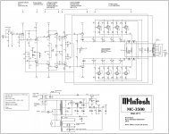
MacIntosh used sweep tubes in one of their high power units, can't remember which one now.
There were at least two high powered "industrial amplifiers" The MI-350 and the MC3500. I believe that they are similar designs using the 6LQ6 / 6JE6C tube.
The Grateful Dead used several MI-350's in their "wall od sound" for huge outdoor concerts. The MI-350 was also used to power the 1969 Woodstock Music Festival.
Attachments
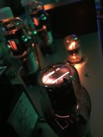
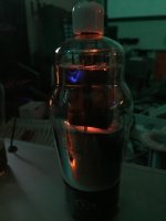
It turned out that a "secret WW-II sweep tube" is capable of 5W of pristine clean sound in SE, with 310V B+ and 4K5 transformers. I wonder though, why Edcor positions them as 15W transformers, if they are capable of 4.5W only down to 110 Hz, then saturate? 😱
-9V bias, 215V stable on G2.
-9V bias, 215V stable on G2.
Attachments
Philips had a AG9007 amplifier with 4x PL36 , that was 1957 !
The 25E5/PL36 also appeared in two early Sansui models; the SM-80 (1961) and the 1000 (1963). Philips' EL36 datasheet gives a class B audio power amplifier alignment.
"The 6HJ5 curves to be found only have one G2 voltage listed but the close cousin, 6DQ5, has a full set."
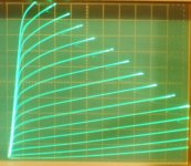
Here are some 6HJ5 grid2 curves.
+8V grid2 steps, starting from 0V for the bottom line. (and +112V for the top curve)
This particular tube gives a 650 mA knee for +150V on grid2 (well above the datasheet spec of about a 550 mA knee [extrapolated by 3/2 power law from 110 Vg2 curves, or from +135Vg2 curves for the 6HD5])
If you need higher grid2 curves than the top +112 V one shown here, you can use a 1.1 power law for current versus voltage on grid2 to re-scale them. (ie, for a 150V top Vg2 curve, with 14 +10.7V Vg2 steps, the Vert. scale factor would change to 69 mA/div, giving about a 650 mA knee as required)
Scale: 50 mA/div Vert. and 50V/div Horiz.
Attachments
Last edited:
Hmmm, minor correction,
I just noticed that extrapolating the 6HJ5 datasheet of a 400 mA knee at 110 Vg2, using 3/2 power law, gives a 637 mA knee at +150 Vg2. My nominal figure of 550 mA at +150 Vg2, that I just mentioned above, is wrong. (bad recall, sorry)
I see I did have a 630 mA knee listed in the "TV Sweeps g2 data list" some ways back, which is closer to the 650 mA knee I am seeing for the present 6HJ5 that just got curve traced. (and closer to the 690 mA knee I had listed for the 6DQ5, a close cousin)
------------------------------------------------------------------------------
"I wonder though, why Edcor positions them as 15W transformers, if they are capable of 4.5W only down to 110 Hz, then saturate?"
How much DC current are you putting through that SE OT? The GXSE-15 I measured once did just hit hard saturation at the 15 Watt level. No room to spare. SE OTs should be de-rated for max power at the max permeability point, or just above, I think. So about 1/2 the Watt ratings given. Those who rave about SE OT performance don't have any idea how badly those things actually perform. 🙄
Last edited:
- Status
- Not open for further replies.
- Home
- Amplifiers
- Tubes / Valves
- 60W with CFB, using Sweep Tube, Full Differential