System efficiency
Actually, it's the combination of a given driver, and the amount of the air load,
as expressed by it's volume.
Highly efficient systems, that reach down deep in the bass, require a very large volume enclosure.They also require quite a bit of cone area. A true infinite baffle is a bit different than a sealed box, but yes, they do share a few basics.
One could also design a very highly efficient ported/or/vented enclosure.
Drivers are specified in terms of "sensitivity" but efficiency is expressed in terms of acoustic output verses voltage input, via a percentage value.
With respect to system Q, a target value of 0.500 would be considered
"critically damped", yet the actual realization of this target Q would largely depends upon the rooms influence. Bessel is 0.577, and maximally flat Butterworth is expressed as 0.707. Again, the actual realization of a target Q is room dependent. It is very possible to design a low Qtc woofer system, say at 0.577 only to have it turn out something closer to maximally flat Butterworth, when loaded into a room's corner.
Thank you. I don't wish to believe something that is wrong. Primarily I'm here to learn and have been fortunate enough to help a couple of people. Thanks for bothering to get back with a reply. I have experience with open baffle and presumed there were similarities.
An open baffle bass system would be among the very LEAST efficient ways of reproducing bass. One is forever fighting against the inevitable front-to-back wave cancellation. It seems to have garnered quite a bit of it's popularity due to it's relatively simple construction requirements.
I have jordan eikona open baffle xd over to 4 12in in U frame quite a way out from front wall and I listen close field, they reach very low with ease
Hi Scott L,
Yes, correct. But I didn't want to get too far into variables.
The classic infinite baffle was the wall of a room. Closing or opening the door could be very destructive to the low frequency radiator - if not comical to others. You can still run across them in homes built from the forties and newer. By the late 60's, that idae was truly dead and gone.
-Chris
@ Myleso
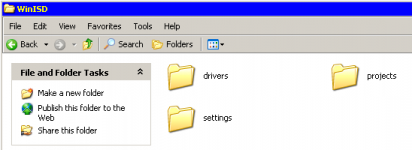
Use the Windows Search for WinISD. Open that folder, then open Projects, then Cut & Paste my file into it. If you havn't already, change the .txt extension to .wpr.
And/or then run WinISD & locate via the arrows, if Projects doesn't show up. Save all your future & existing Projects in Projects. Next time you run WinISD you should see Projects easily.
Im sorry but the projects folder just doesn't exist for me. I have the updated version and everything :/ Thanks so much for your effort but I think I am just going with the 2 Cubic ft sealed enclosure fir the Dayton 12'' HF Reference subwoofer.
Somthing I need help with is the amp. I am looking at the MiniDSP PWR-ICE 125. I like the options the DSP provides but It has an RMS of 450 W which is more than I need. Is it worth going for this one or would one of the 300W Yung or Bash plate amps from Parts Express be just as good? Thanks!
Sealed, Infinite Bafffle
Hi Chris,
There has been a very small resurgence of interest, as promoted by the "Cult of the Infinitely Baffled". I built one into my house in 2009. I discovered soon thereafter that I needed to build the rest of the system to match. It's been now accomplished, and is truly astounding !
Hi Scott L,
Yes, correct. But I didn't want to get too far into variables.
The classic infinite baffle was the wall of a room. Closing or opening the door could be very destructive to the low frequency radiator - if not comical to others. You can still run across them in homes built from the forties and newer. By the late 60's, that idae was truly dead and gone.
-Chris
Hi Chris,
There has been a very small resurgence of interest, as promoted by the "Cult of the Infinitely Baffled". I built one into my house in 2009. I discovered soon thereafter that I needed to build the rest of the system to match. It's been now accomplished, and is truly astounding !
The term "efficiency" shows up quite a bit in these threads.Drivers are specified in terms of "sensitivity" but efficiency is expressed in terms of acoustic output verses voltage input, via a percentage value.
Easy, but unhelpful, to glibly quote the physics textbook as if that explained everything.
How do you reckon the "efficiency" of a ported box when the port adds to the loudness above a certain frequency, blocks the output at a certain frequency, and subtracts from the loudness (at 18 dB/8ave if I recall correctly) below that?
So not straightforward figuring how much sound you "efficiently" get to your ears in a typical music room with a dipole or gigantic baffle board. Or how that compares to other boxes.
Basically, the crude Rice-Kellogg driver shakes - weakly - pretty much the same air whenever used as a direct radiator and the rear wave has access to your ears. Horn loading is the way to change "efficiency" by transforming acoustic impedance.
The issue is further muddied by the disconnect between electric watt counting and acoustic watts. You can destroy your hearing with less than .1 acoustic watts (and many music fans do just that). Without fussing about all that burning coal and gas, seems like crummy engineering to make .1 of a watt of sound with a 500 watt amp.
Ben
Last edited:
@ Myleso
My Computer/LOCAL DISK (C)/Documents and Settings/User Name/My Documents/WinISD
Maybe the reason it doesn't exist, is because you haven't created a project yet with the latest version ? If you had you would see it, & find it with the search i mentioned.
2 things to try.
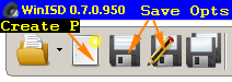
1 - Create a new Project, anything at all, Save it & see if a Projects folder is made.
2 - Just make a new folder in the WinISD program folder called projects. Paste my file in there & run WinISD & you should be able to use it.
Even if your mind is made up with what build you are making this time, it's good to get things sorted for the future 😉
My Computer/LOCAL DISK (C)/Documents and Settings/User Name/My Documents/WinISD
Maybe the reason it doesn't exist, is because you haven't created a project yet with the latest version ? If you had you would see it, & find it with the search i mentioned.
2 things to try.
1 - Create a new Project, anything at all, Save it & see if a Projects folder is made.
2 - Just make a new folder in the WinISD program folder called projects. Paste my file in there & run WinISD & you should be able to use it.
Even if your mind is made up with what build you are making this time, it's good to get things sorted for the future 😉
Attachments
Hi Ben,
Just for a reference, most speaker systems in residential service have a -3dB point above 60 Hz. Note that I have been using -3 dB points, not the -10 dB (or -20 dB) limits most speaker manufacturers do. The enclosures I've designed are for the most part, significantly larger than commercial speakers.
Why are most speakers 1/2 the size, or lower, than the optimal size for a woofer? Because, speakers are heavy, reinforced boxes of air being shipped all over the globe. That's why they are made small and with thin walls. That and the material cost to begin with. But you can't blindly expand the box volume and expect everything to turn out well.
System Q. The Butterworth response suits speakers well because it extends the bass response lower than others with good damping. A Q of around 0.5 (more Bessel) actually begins to roll the bass off much earlier than the Butterworth. With it's improved phase characteristics, the Bessel alignment is better suited to midrange and tweeter duty. In case someone hasn't considered this, even tweeters have a system Q and a box behind the diaphragm. It's just normally built into the tweeter or midrange assembly that you buy. Midrange drivers that look like a small woofer with a solid metal back will have a high "Q" and therefore a peaky response. Not good in a midrange. Some are made with a box (extended rear section), or no box at all and they really do look like small woofers. You have to make a box for it following the same math and equations that you do for the bass driver.
The laws of physics will cover all aspects of speaker design. No one is exempt Ben.
The one thing we agree on is that systems should be designed for acoustical output to fit the application, not to being able to list higher power levels. The goal is to excite the air, not to dissipate electrical watts. That is where the industry took a wrong turn so many years ago. The public and sales people (for audio) have driven this bus off the road, not the engineers.
-Chris
But the laws of physics do govern how any acoustic radiator is going to work. You can't just make a huge box for a large speaker, you absolutely must consider both the average room size for that boxed system, and the characteristics of that particular driver.Easy, but unhelpful, to glibly quote the physics textbook as if that explained everything.
That's an easy question to answer! Really easy, and if you had an understanding of how these systems actually operate, you wouldn't have posted that. It is true that lower than system resonance (my designs are normally Qts = 0.7 ish) the port unloads the woofer. Therefore, good ported systems either have very low resonance (mine typically run from about 20 Hz (-3 dB) to around 40 Hz (-3dB)) where most of that energy is noise and is filtered out before the amplifier, or designed with a roll-off below box resonance. Around the resonant frequency, the port adds damping to the woofer which reduces the excursion (a lot!) and therefore distortion. Well above this critical area, the operation is the same as a sealed box. If you understand how ported systems work, you can design one heck of a nice system around it.How do you reckon the "efficiency" of a ported box when the port adds to the loudness above a certain frequency, blocks the output at a certain frequency, and subtracts from the loudness (at 18 dB/8ave if I recall correctly) below that?
Just for a reference, most speaker systems in residential service have a -3dB point above 60 Hz. Note that I have been using -3 dB points, not the -10 dB (or -20 dB) limits most speaker manufacturers do. The enclosures I've designed are for the most part, significantly larger than commercial speakers.
Why are most speakers 1/2 the size, or lower, than the optimal size for a woofer? Because, speakers are heavy, reinforced boxes of air being shipped all over the globe. That's why they are made small and with thin walls. That and the material cost to begin with. But you can't blindly expand the box volume and expect everything to turn out well.
System Q. The Butterworth response suits speakers well because it extends the bass response lower than others with good damping. A Q of around 0.5 (more Bessel) actually begins to roll the bass off much earlier than the Butterworth. With it's improved phase characteristics, the Bessel alignment is better suited to midrange and tweeter duty. In case someone hasn't considered this, even tweeters have a system Q and a box behind the diaphragm. It's just normally built into the tweeter or midrange assembly that you buy. Midrange drivers that look like a small woofer with a solid metal back will have a high "Q" and therefore a peaky response. Not good in a midrange. Some are made with a box (extended rear section), or no box at all and they really do look like small woofers. You have to make a box for it following the same math and equations that you do for the bass driver.
The laws of physics will cover all aspects of speaker design. No one is exempt Ben.
No it isn't Ben. It's well known that there is an acoustical impedance mismatch between a driver (speaker) and the air. That is why a horn is sometimes referred to as an acoustical transformer - to match the speaker radiation impedance to the low impedance of the standing air in a room. The same process works in reverse in your ears. It is not an efficient process by any measure, but it is all we have.The issue is further muddied by the disconnect between electric watt counting and acoustic watts.
No crummy engineering involved. The public has voted the large box down, not the engineers. Engineers build what will be bought, they must built to demand. So if you want to point at anyone for the state of acoustic engineering, point around the room at everyone but the engineer! It seems they did a fine job with large enclosures earlier in time, and once Thiel and Small came out with their work, speaker enclosure design became a science. After all, the enclosure-speaker combination is a high pass filter. Same for the infinite baffle system. So I can't see what point you are trying to make at all. Everything is described correctly for all aspects of speaker system design, and there are definite box sizes for each acoustic radiator design. You can either build to a plan with clear expectations, or you can throw caution to the wind and bang something out similar to what you have been suggesting.Without fussing about all that burning coal and gas, seems like crummy engineering to make .1 of a watt of sound with a 500 watt amp.
The one thing we agree on is that systems should be designed for acoustical output to fit the application, not to being able to list higher power levels. The goal is to excite the air, not to dissipate electrical watts. That is where the industry took a wrong turn so many years ago. The public and sales people (for audio) have driven this bus off the road, not the engineers.
-Chris
Hi Y'all,
Post #81: "...efficiency is expressed in terms of acoustic output verses voltage input, via a percentage..."
I'm sure that's just a typo, but, efficiency is output power divided by input power, and if you want it in percent you multiply by 100.
Efficiency and sensitivity conversion - loudspeaker percent and dB per watt and meter loudspeaker efficiency versus sensitivity vs speaker sensitivity 1 watt = 2,83 volt box chart - sengpielaudio Sengpiel Berlin
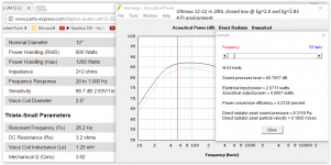
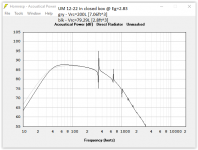
A simulator can answer the basic question about the "margin of error" pretty easily. As long as you don't go too small the margin is very wide. Often the recommended sealed volume leans already towards the minimum (If you simulate w/ this volume you see a straight line low end slope followed by a bit of a hump.).
Attached, find a Hornresp simulation of the Ultimax UM 12-22 in a closed box.
As has been said before, with sound in general and particularly at the low end, the room dominates.
Regards,
Post #81: "...efficiency is expressed in terms of acoustic output verses voltage input, via a percentage..."
I'm sure that's just a typo, but, efficiency is output power divided by input power, and if you want it in percent you multiply by 100.
Efficiency and sensitivity conversion - loudspeaker percent and dB per watt and meter loudspeaker efficiency versus sensitivity vs speaker sensitivity 1 watt = 2,83 volt box chart - sengpielaudio Sengpiel Berlin
A simulator can answer the basic question about the "margin of error" pretty easily. As long as you don't go too small the margin is very wide. Often the recommended sealed volume leans already towards the minimum (If you simulate w/ this volume you see a straight line low end slope followed by a bit of a hump.).
Attached, find a Hornresp simulation of the Ultimax UM 12-22 in a closed box.
As has been said before, with sound in general and particularly at the low end, the room dominates.
Regards,
Attachments

Yes, basically if the room doesn't support below a certain frequency, you'll waste a lot of power to create sound below that. Same thing said a different way.
-Chris
-Chris
right track, man
@Myleso -
I don't think anyone responded to this post!
You are on the right track now.
Keep playing around in WinISD and you will find some combination
that will be perfect for your needs.
Bring up the "Cone Excursion" screen at the top, then choose "Filter" on
the lower left -put in a High Pass Filter at 20Hz.
See how that really helps excursion problems?
Oh, BTW, if a driver has an xmax of, say 12mm, it's totally ok in modeling to add 10-15% to that, so you are modeling then with an xmax of 13.8mm.
If you still have excursion to "spare", then you can add another filter, a "Parametric" filter at 30 Hz and add 2 dB of boost at that frequency.
In this manner you can precisely tune a sub to your needs.
Hope this helps!
Okay so I had a quick look at the 12'' version of the same driver and it is attractive for several reasons. For starters, it is more sensitive at 90.3 dB 2.83V/1m as opposed to 87.8 dB 2.83V/1m in the 10''. Secondly it has an extra 2mm Xmax and last it has a slightly lower Fs.
When I simulate these two drivers next to each other in, both in 1.3 ft^3 boxes (as close to 0.707 Qts as possible for both drivers), the 10'' version shows a better bass response as shown in this picture View attachment 597785. YELLOW -12'', PINK- 10''
Apart form the bass response, the 12'' seems much better. It doesn't exceed Xmax with even its rated RMS (the 10'' did very easily), Its max SPL is better across all frequencies and its maximum power is far better all over too. View attachment 597786
Can I eq the 12'' to have a flatter response a low frequencies? I have read a little about the Linkwitz transform and it sounds like it will flatten the response at lower frequencies at the cost of power. Is that right?
here is each drivers SPL through the frequency spectrum at 50W input.View attachment 597787
@Myleso -
I don't think anyone responded to this post!
You are on the right track now.
Keep playing around in WinISD and you will find some combination
that will be perfect for your needs.
Bring up the "Cone Excursion" screen at the top, then choose "Filter" on
the lower left -put in a High Pass Filter at 20Hz.
See how that really helps excursion problems?
Oh, BTW, if a driver has an xmax of, say 12mm, it's totally ok in modeling to add 10-15% to that, so you are modeling then with an xmax of 13.8mm.
If you still have excursion to "spare", then you can add another filter, a "Parametric" filter at 30 Hz and add 2 dB of boost at that frequency.
In this manner you can precisely tune a sub to your needs.
Hope this helps!
what do you think the reason it will be?I'd guess at ±5% by volume to be a top limit and only just being audible.
I built a 72litre tall floor stander a while back. When I came to test the final build I decided there was too much volume in the box. After some further testing using blocks of MDF inside, I decided to saw 5" off the bottom and reseal.
That took off ~14% from the internal volume. It was very definitely different sounding.
It certainly measured differently.
maybe it's not because of the size, just because it(the bigger box) not strong/rigid enough?
The box was assembled from fairly narrow panels >=30mm thick (kitchen work-top). It was definitely not flexing sufficiently to affect the performance.
It was the internal volume that needed to be changed. My room temperatures may be different from the speaker Designers home.
Doing a speaker box test after assembly confirmed it was too big. Altering the length of the adjustable vents could not correct the as built error.
The best solution was to reduce the box volume and then tune the vents to the new size. Initially with dummy blocks inside and the final solution was to saw a length off the height.
Last edited:
Hi Andrew,
You could have used some more dense stuffing behind the woofer. This would have absorbed more of the midrange coming off the rear of the cone and bouncing back through the cone material. It would have sounded cleaner as a result. Sawing the box was a dramatic reaction to a simple problem.
The temperature differential between your home and that of the designer would never be enough to explain the difference in box volume. If you didn't test the actual drivers yourself first, I can see that as being a normal manufacturing tolerance. Who knows, after a year or so, maybe the woofer will have loosened up enough to want that originally sized enclosure.
I'll bet they sound good though.
-Chris
it is partially stuffed with long hair wool, but located to maintain the resonances required of a vented cabinet.
Mid range is not a problem. Maybe because it is a 3way crossing @ ~400Hz.
I did a full t/s before starting the build. I did a winisd before starting the build. I adjusted the speaker cable resistance to one bass driver to correct for a small difference in driver Q after getting the t/s and win isd to confirm what was required.
I then tested the as built and checked the final Q using the set up suggested by R.B.Bullock in "Bullock on boxes". A very good pamphlet for vented speakers. CAD speaker software was in it's infancy back then and Bullock supplied some code for use with slow monochrome computers.
And this was my third set of speakers, all kits, and I knew that running in of the surrounds and spiders did change the t/s parameters. Temperature has BIG effect on the driver resonance.
Hi Andrew,
I wrote my own routines and ran them on an original IBM PC. The output was on paper. This agreed with the program I wrote for my TI-58C where I had to write down a few key values. Yes, those monochrome days were trying compared to what we have today. But, the math worked and my enclosures turned out as programmed. I used to generate my own T/S values from driver measurements.
The only temperature that really matters is the VC temperature. Ambient room temperatures don't matter nearly as much, not at all in comparison. Not unless you cool Vifa woofers, they actually do freeze solid!
You can use more long haired wool behind the woofer while still allowing free air movement. Later once the woofers relax, you can remove the pad you designed in for this purpose. How much different was the % volume?
-Chris
I think the change was -14% (it was ~1990/91). From ~72litres down to ~60litres, tested in stages by adding MDF blocks inside the cabinet.
It was based on that quite audible change that I first posted that a tolerance on volume should in my opinion be around 5%.
It was based on that quite audible change that I first posted that a tolerance on volume should in my opinion be around 5%.
I'd guess at ±5% by volume to be a top limit and only just being audible.
Hi all,
Interesting thread, ...very relevant to my first attempt at DIY... an attempt where I haven't just copied others' posted designs, and finally take the time to learn some design software including HR 😱
Ok...I'm starting out slow....I've chosen an 18" that appears to be suitable for either sealed or vented....and well, I am still kind of copying again... the 18" is the BMS 18N862 that Josh Ricci's most excellent data-bass reviewed, both sealed and vented.
So to learn, I'm currently building both a sealed and vented box with this same driver....
Where I'm getting confused in this thread, is about what does the air spring actually do.
One view put forth is that "The only thing the air spring does is prevent overexcursion (assuming the amp is sized appropriately)."
I get that a smaller box helps prevent over excursion, but doesn't a box's volume also effect transient response and help control freq response ripple? At least that's what Eminence designer and other literature I've read says....
I'm planning on building my sealed box for 'maximally flat', Qtc=.707
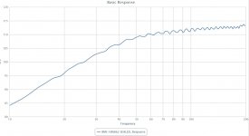
I see the 4 cu ft box used on data-bass's sealed 18N862 is a little larger than than maximally flat with a Qtc of about .64
here's a snip of it's response from data-bass....
Does volume have an effect on the ripple displayed?
If not what does?
Thx, Mark
Interesting thread, ...very relevant to my first attempt at DIY... an attempt where I haven't just copied others' posted designs, and finally take the time to learn some design software including HR 😱
Ok...I'm starting out slow....I've chosen an 18" that appears to be suitable for either sealed or vented....and well, I am still kind of copying again... the 18" is the BMS 18N862 that Josh Ricci's most excellent data-bass reviewed, both sealed and vented.
So to learn, I'm currently building both a sealed and vented box with this same driver....
Where I'm getting confused in this thread, is about what does the air spring actually do.
One view put forth is that "The only thing the air spring does is prevent overexcursion (assuming the amp is sized appropriately)."
I get that a smaller box helps prevent over excursion, but doesn't a box's volume also effect transient response and help control freq response ripple? At least that's what Eminence designer and other literature I've read says....
I'm planning on building my sealed box for 'maximally flat', Qtc=.707
I see the 4 cu ft box used on data-bass's sealed 18N862 is a little larger than than maximally flat with a Qtc of about .64
here's a snip of it's response from data-bass....
Does volume have an effect on the ripple displayed?
If not what does?
Thx, Mark
Attachments
Where I'm getting confused in this thread, is about what does the air spring actually do.
It's a mechanical damper, it provides resistance. Added resistance is always a loss. This is why more power is required to reach excursion limits in a small sealed box.
Is a mechanical damper necessary? Some people seem to think so, I think not. Not when you have electrical limiters available and when common sense limiting is as easy as turning down the volume knob when it sounds bad.
There's something else a stiff air spring does too, something most people probably have not considered. It increases distortion. Since air does not compress and expand in exactly the same way you get extra distortion with every cycle. How much extra distortion you get depends on how big the box is in relation to how much air is being moved. A very small sealed box with a very large driver moving at huge excursion is the worst case.
A quick sim will answer the rest of your questions. There shouldn't be much ripple at all in a sealed box of reasonable dimensions. The pic you included shows a normal amount of ripple, this is normal, all measurement are a bit wiggly and it won't go away if you put the driver in a larger box. The ripple in the response that is controllable is a larger, often wider sort of ripple that is causes by resonances and/or diffraction. Resonances can come from different causes but in a sealed box the only resonance is related to the box dimensions and is going to be pretty mild if the box is sealed. Nothing to worry about unless your box dimensions are pretty unusual.
Last edited:
- Status
- Not open for further replies.
- Home
- Loudspeakers
- Subwoofers
- How big is the margin of error for a sealed cabinet subwoofer?