Sometimes I feel like insulting native english speakers for their poor use of english. Thay haveno excuses.
I can always forgive non native speakers. They at least try to talk/type our silly language.
I was hopeless at foreign languages at school, so untimately I became a teacher.


you would be surprised at the situation in my home/ how i grew up,...... mother speaks 'Marathi' language, father speaks ' Kannada' language.... and in school i learnt 'English' as a third language and all movies that i watched were in 'Hindi' language....
I do not have mastery in any language...... but still some how still surviving...
I believe, its the situation with most Indians , they know atleast three or more languages easily.... Jack of all trades...but master of none
Last edited:
Your English fine Prasi. I'm sorry if my message gave you the impression it wasn't. I had understood perfectly what you meant about the diodes. Being a newbie, I just needed confirmation that I could do that.yes, again.... i take that leaving all diodes means keeping all in....
sorry my English is poor and recently i was 'insulted' for my poor English on this technical forum...what an irony🙄
Shame on the guy who insulted you. That's wrong, mean and just plain silly. I just recently discovered this forum and, in addition to all the great advice, I love how it brings some many people together from all over the world. So thanks again for helping me out.
I posted in the V2 board but haven't gotten a response. I built the V2 board using the V2 BOM- when I tested it, both LEDs lit continuously and the circuit did not shut off when I tested for DC. I read that the transistor polarities might be wrong.
Is the V2 board designed for EBC or ECB?
Is the V2 board designed for EBC or ECB?
I posted in the V2 board but haven't gotten a response. I built the V2 board using the V2 BOM- when I tested it, both LEDs lit continuously and the circuit did not shut off when I tested for DC. I read that the transistor polarities might be wrong.
Is the V2 board designed for EBC or ECB?
V2 sch shows 2sc945 which is ecb and c9013 is ebc. this is what my build uses (i built V2 ) and works perfect. check for diode orientation. if you have an ebay transistor tester, its quite easy to find the pinouts plus confirm that the tranny is alive... something like this http://www.ebay.com/itm/LCR-T4-ESR-...407715?hash=item25b3ec73a3:g:k3wAAOSwCQNWgllX
Last edited:
Well, I made a mess of my V2 board trying to desolder the relays. I'm going to start over with the V3 board but mouser #653-G5LA-14-CF-DC12 for K1, K2 (24 volt) is unavailable.
Would this (http://www.mouser.com/Search/ProductDetail.aspx?R=653-G5Q-14-DC12) be a good sub?
Would this (http://www.mouser.com/Search/ProductDetail.aspx?R=653-G5Q-14-DC12) be a good sub?
Hey mattmcl,
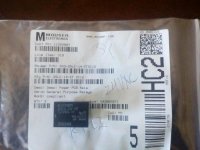
I got these, 653-G5LE-14-CFDC12. See image. I'm pretty sure I compared with the BOM ones and they were similar. Pinout matches the PCB. I haven't soldered them in yet so if anybody sees that they won't work let me know. I ordered them a couple months ago so I would think they are still in stock.
I got these, 653-G5LE-14-CFDC12. See image. I'm pretty sure I compared with the BOM ones and they were similar. Pinout matches the PCB. I haven't soldered them in yet so if anybody sees that they won't work let me know. I ordered them a couple months ago so I would think they are still in stock.
Attachments
those wont fit the pcb as footprint and pin spacing are different.Would this (http://www.mouser.com/Search/ProductDetail.aspx?R=653-G5Q-14-DC12) be a good sub?
see my post no. 256 . just ensure that PCB silk outline for relays can take 22mm lengthwise.
653-G5LE-14-CFDC12 would work too as given by dbis
Last edited:
those wont fit the pcb as footprint and pin spacing are different.
see my post no. 256 . just ensure that PCB silk outline for relays can take 22mm lengthwise.
653-G5LE-14-CFDC12 would work too as given by dbis
Thanks! Do you happen to have a replacement for 78THLR6400 and 78THLR6405 (LEDs)?
I think I ordered 78-TLHR6400 and 78-TLHG6405 from Mouser for those but maybe I got the BOM numbers wrong. They are both still in stock though. Anyway I'm not sure how much it matters if you get the ones on the BOM. I haven't powered my board up yet.Thanks! Do you happen to have a replacement for 78THLR6400 and 78THLR6405 (LEDs)?
any generic led would do. i used a green and yellow 5mm ones from a local store, works just fine.Thanks! Do you happen to have a replacement for 78THLR6400 and 78THLR6405 (LEDs)?
my feeling only... it would have been nice if the suggestions given by me or some one else (AndrewT), if implemented, there is some sort of feedback from those that implemented. it would help other builders too ...
otherwise it seems to i am/others are doing unhelpful job in this thread.
Prasi
otherwise it seems to i am/others are doing unhelpful job in this thread.
Prasi
my feeling only... it would have been nice if the suggestions given by me or some one else (AndrewT), if implemented, there is some sort of feedback from those that implemented. it would help other builders too ...
otherwise it seems to i am/others are doing unhelpful job in this thread.
Prasi
I so appreciate your and Andrews help and will post back when I've had time to get back to my build. Personally I don't always have the time I'd like to devote to my hobbies.
my feeling only... it would have been nice if the suggestions given by me or some one else (AndrewT), if implemented, there is some sort of feedback from those that implemented. it would help other builders too ...
otherwise it seems to i am/others are doing unhelpful job in this thread.
Prasi
Hi Parsi,
Good point. I'll let you know how it goes when I add the speaker protection circuit to my F5. Right now I'm kind of breaking the F5 in for a couple weeks. Then I'll check the biases and offset again and if everything is ok add the speaker pcb. Thanks.
nothing against you guys, you are recent to this thread. i was searching the thread and i came across posts by me more than a year ago and i saw no replies.
AndrewT has even older posts and in previous versions too!
reg
Prasi
AndrewT has even older posts and in previous versions too!
reg
Prasi
Just want to add that I'd be pretty helpless without you guys so I will certainly follow up on any advice to let you know how it went and also help any future DIYers out. Thanks again.
yes! thats the spirit!.
Once any newbie reads the whole thread, he should have answers to most of his doubts! thats how forums/threads work... only specific details/ difficulties need be answered here.
again such answers help more newbies.... like a database of info...you keep on improving and adding more info.
reg
Prasi
Once any newbie reads the whole thread, he should have answers to most of his doubts! thats how forums/threads work... only specific details/ difficulties need be answered here.
again such answers help more newbies.... like a database of info...you keep on improving and adding more info.
reg
Prasi
Hi Prasi,
A shout to you and Andrew for your help and suggestions to the builders here. I haven't got to ordering the boards and parts yet, hence the silence. 🙂
A shout to you and Andrew for your help and suggestions to the builders here. I haven't got to ordering the boards and parts yet, hence the silence. 🙂
Hi Prasi,
I can only speak for myself in saying that I am very appreciative of all the help and advice I've received on this site. You, Andrew, 6L6, and Dennis Hui have been imensly helpful to me with your contributions. Your relay suggestion seems to fit the pin layout on the board, but I as well haven't had any downtime to actually begin assembling and testing anything yet. I will report back when I do so that I can help (hopefully) someone who may have had the same questions. 😊
I can only speak for myself in saying that I am very appreciative of all the help and advice I've received on this site. You, Andrew, 6L6, and Dennis Hui have been imensly helpful to me with your contributions. Your relay suggestion seems to fit the pin layout on the board, but I as well haven't had any downtime to actually begin assembling and testing anything yet. I will report back when I do so that I can help (hopefully) someone who may have had the same questions. 😊
my feeling only... it would have been nice if the suggestions given by me or some one else (AndrewT), if implemented, there is some sort of feedback from those that implemented. it would help other builders too ...
otherwise it seems to i am/others are doing unhelpful job in this thread.
Prasi
Thank you very much for your contributions Prasi.
I just built two of these circuits and they do work correctly as far as delay.
As for DC protection, I know they work because I tested them with a 9V baterie in the bench... never had the oportunity to verify if they work fast enough if anything goes wrong with my amps..... Good
- Home
- The diyAudio Store
- Speaker Turn On Delay and DC Protector Board Set (V3)