BTW, Abraxalito drew my attention to this YJ Hifi STA326 - it uses a superior AK4113 spdif-i2s receiver but has noisy regs - it is much easier to replace regulators than an smd receiver. The USB is low grade but at $35... https://world.taobao.com/item/52531...z0k.7386009.0.d4919233.sboQ1C&_u=t2dmg8j26111
Ti won't give me samples at my .edu email anymore, I won't order anything from them anymore either - quid pro quo.
So, I just tried to order a TPA3251d2EVM at 50% off with coupon TPA32CES and now it let me add samples to the order. Has anyone else had this experience?
This seems pretty interesting:
Integrated DSP Digital HiFi Power Amplifier 100W USB DAC Audio Decode 24Bit/192K
Lots of discrete components, direct SPDIF input to chip etc
Integrated DSP Digital HiFi Power Amplifier 100W USB DAC Audio Decode 24Bit/192K
Lots of discrete components, direct SPDIF input to chip etc
From what I read that one is already replaced by a newer model. The D2P has some errors. I think you can find them here on the forum.
This seems pretty interesting:
Integrated DSP Digital HiFi Power Amplifier 100W USB DAC Audio Decode 24Bit/192K
Lots of discrete components, direct SPDIF input to chip etc
Price seems a little high (940rmb equivalent) - I have several which I paid 358rmb for including PSU. To be avoided unless you're happy to correct the errors JP has mentioned. I've blogged about it here : http://www.diyaudio.com/forums/blogs/abraxalito/1380-goosebumping-headphone-dac-amp.html
Thanks guys for steering me away from an expensive mistake.
What about this one then...??
HIRESFI AMPER502 True Digital Amplifier STA350BW WM8805
What about this one then...??
HIRESFI AMPER502 True Digital Amplifier STA350BW WM8805
Thanks guys for steering me away from an expensive mistake.
What about this one then...??
HIRESFI AMPER502 True Digital Amplifier STA350BW WM8805
It seems the be designed in Germany About Us so it might be worth trying.
Thanks guys for steering me away from an expensive mistake.
What about this one then...??
HIRESFI AMPER502 True Digital Amplifier STA350BW WM8805
It might be OK, someone has to try and report on these things first 🙂
There are quite a few similar amps around now, which have their own strengths and weaknesses. To choose between them, what will be your main input source to the amp and how important to you are a) Usb input b) Coax digital, c) Optical Toslink d) Analogue input. And lastly do you have very sensitive speakers and/or listen very close to them?
Thanks guys for steering me away from an expensive mistake.
This is the next-generation model which fixes the mistakes in the original one -
https://item.taobao.com/item.htm?spm=a230r.1.14.57.HThuTt&id=19260362926&ns=1&abbucket=18#detail
The basic model has no USB input, that comes as a plug-in module for slightly more money. But remote comes as standard. Power supply isn't included in the basic price.
Is this model sonically better than the D802?
I haven't tried the D802 but seeing its based on STA326 I'd say there wouldn't be much to choose between them. The Popu has more potential to upgrade because the output stage is discrete hence you could increase the power rail voltage considerably by replacing the output FETs and re-jigging the power supplies.
I probably find a solution for that annoying auto mute of the D802. In the datasheet of the STA326:
http://www.st.com/content/ccc/resou...df/jcr:content/translations/en.CD00062804.pdf
At page 31 is the description of the bit ZDE from configuration register D. ZDE is "Zero detect mute enable" which means after 2048 samples of zero, it auto mutes the corresponding channel.
My solution in short, I simply attached a micro controller (in my case an ESP8266) to the the I2C pads near the display and set the ZDE bit to 0. This works and the auto mute is off and now there are no more clicks between audio tracks.
Unfortunately this bit is enabled again after reset, also the MCU of the D802 resets this bit every time switching on the amp. But as far as I figured out, the MCU does not touch the register D after that.
So my idea is to connect a small MCU (maybe an ATtiny) to I2C, which wakes up at switch on and about 10s later set the ZDE bit to 0.
Also there is another auto mute bit: IDE in register F (page 34). This bit means "invalid input detect auto-mute enable" and mutes the output if there is no valid input data. This bit also is enabled by default, but thats ok I think.
This is the next-generation model which fixes the mistakes in the original one -
https://item.taobao.com/item.htm?spm=a230r.1.14.57.HThuTt&id=19260362926&ns=1&abbucket=18#detail
The basic model has no USB input, that comes as a plug-in module for slightly more money. But remote comes as standard. Power supply isn't included in the basic price.
Howdy Abraxalito. In that listing you posted, it appears the maker is "Popu" and the product is "Mercury". If you scroll down the listing a ways, there appears to be a "Mercury Pro".
I read zero Chinese, so can't discern any of the differences between the Pro and non-Pro. (Other than color.) But it looks like the inductors on the Pro are maybe bigger, and maybe it supports a higher supply voltage as well?
By the way, if you don't want to go the Taobao route, I found the new version on ebay: POPU Mercury 80W*2 Pure Digital USB/COAXILAL/RCA Power Amplifier 192KHZ/24Bit, seller "forexmen". Price is $140 to $160 USD, depending on options. I can't find the "Pro" version on ebay.
I also checked AliExpress, couldn't find the updated version. What were the mistakes of the original?
Howdy Abraxalito. In that listing you posted, it appears the maker is "Popu" and the product is "Mercury". If you scroll down the listing a ways, there appears to be a "Mercury Pro".
Hi Matt - yeah they have four or five options, the 'Pro' one being the most expensive with all the bells and whistles (higher voltage supply being one).
I read zero Chinese, so can't discern any of the differences between the Pro and non-Pro. (Other than color.) But it looks like the inductors on the Pro are maybe bigger, and maybe it supports a higher supply voltage as well?
Yeah and also the USB might be more capable too, not sure about that. They offer different USB interface chips.
By the way, if you don't want to go the Taobao route, I found the new version on ebay: POPU Mercury 80W*2 Pure Digital USB/COAXILAL/RCA Power Amplifier 192KHZ/24Bit, seller "forexmen". Price is $140 to $160 USD, depending on options. I can't find the "Pro" version on ebay.
Seems a bit pricey in that I paid about $52 for the most basic one including PSU. A Taobao agent surely can get you a much better price than $140. The 'Pro' one is probably going to run about $100.
I also checked AliExpress, couldn't find the updated version. What were the mistakes of the original?
Check my blog here - http://www.diyaudio.com/forums/blogs/abraxalito/1380-goosebumping-headphone-dac-amp.html
The TL,DR answer is the 2n2 caps (8 in total) feeding the FET gates need increasing to around 6.8nF (minimum)
I probably find a solution for that annoying auto mute of the D802. In the datasheet of the STA326:
http://www.st.com/content/ccc/resou...df/jcr:content/translations/en.CD00062804.pdf
At page 31 is the description of the bit ZDE from configuration register D. ZDE is "Zero detect mute enable" which means after 2048 samples of zero, it auto mutes the corresponding channel.
My solution in short, I simply attached a micro controller (in my case an ESP8266) to the the I2C pads near the display and set the ZDE bit to 0. This works and the auto mute is off and now there are no more clicks between audio tracks.
Unfortunately this bit is enabled again after reset, also the MCU of the D802 resets this bit every time switching on the amp. But as far as I figured out, the MCU does not touch the register D after that.
So my idea is to connect a small MCU (maybe an ATtiny) to I2C, which wakes up at switch on and about 10s later set the ZDE bit to 0.
Also there is another auto mute bit: IDE in register F (page 34). This bit means "invalid input detect auto-mute enable" and mutes the output if there is no valid input data. This bit also is enabled by default, but thats ok I think.
For me I don't think it's not worth to hassel with that.
My son hate to play games with this amp when it's suddenly go to mute and he got killed beacause he can't hear the enemy sneaking to him.
😀
I am thinking about to use a Digispark (Digispark USB Development Board - Digistump), which can be bought on ebay for about 2-3 EUR.
Putting a program to this Digispark is very simple and strait forward. Further it needs 4-5 wires to the board of the D802. So this all is pretty simple.
I ordered some of these Digiskark, and if I get it to work, I will post here how to make it.
Putting a program to this Digispark is very simple and strait forward. Further it needs 4-5 wires to the board of the D802. So this all is pretty simple.
I ordered some of these Digiskark, and if I get it to work, I will post here how to make it.
I am thinking about to use a Digispark (Digispark USB Development Board - Digistump), which can be bought on ebay for about 2-3 EUR.
Putting a program to this Digispark is very simple and strait forward. Further it needs 4-5 wires to the board of the D802. So this all is pretty simple.
I ordered some of these Digiskark, and if I get it to work, I will post here how to make it.
I'll be very interested to read "how to" - hope it works!
Unfortunately I can not get it to work with the Digispark, but with the ESP8266 it works. If I connect 2 wires from the Digispark to the I2C (no power for Digispark), then it seems that the MCU of the D802 cannot communicate through I2C. I tried inline resistors and pull-ups, nothing helped. So maybe some hardware differences on the pins of the ATtiny and the ESP8266 are the reason.
The ESP8266 is not as easy to put a program on it as the Digispark, but still very simple. The ESP8266-01 module is also a little smaller than the Digispark, but requires a programmer, like this one:
USB Seriell Adapter Breakout ESP-01 ESP8266 Programmer, Testplatine Arduino | eBay
The ESP8266-01 modules are also very cheap:
ESP8266 Esp-01 Serial Transceiver WIFI Wireless Modul AP+STA Arduino Technik Neu | eBay
A NodeMCU is based on the ESP8266 has the programmer on board but is rather big, may to big to put it inside the D802:
NodeMcu Lua WIFI Netzwerk entwicklungs-board basiert ESP8266 CP2102 Board | eBay
My prototype now is running click free music for about 2 hours without problems. If I clean up all things I will post a how to.
So here is a little how to for the D802 auto mute (click) fix. I'm using it on the D802C, but it should also work with the D802.
Needed:
- ESP8266-01 Module
- A Programmer or USB2Serial adapter (3.3V!), see my post before
- 5 wires
- A diode (1N4001, 1N4150, ...), we need 0.7V drop
We need this diode, because the ESP8266 is 3.3V and not 5V tolerant, but maybe it works without this diode.
Programming the ESP8266:
To put the program onto the ESP8266 you have to install the Arduino IDE. Inside the Arduino IDE you have to install the ESP8266 platform. A good tutorial can be found here:
ESP8266 - Easiest way to program so far (Using Arduino IDE)
https://github.com/esp8266/Arduino
In the Arduino IDE, load my code and press the check mark to compile. If there are no errors, connect the ESP and programmer/serial interface and upload the code by pressing the arrow button.
Wiring the ESP8266 to the D802:
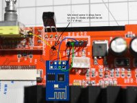
Near the OLED display there are 5 solder pads (GND, SDA, SCL, 5V, 3.3V), here we have the I2C bus. Also we need one pad near the rotary encoder (on a DMM you should get about 4.3V here). On my photo I soldered some pin headers here.
Wiring ESP -> D802:
GND -> GND
VCC -> 3.3V
GPIO2 -> SDA
GPIO0 -> SDL
CH_PD -> Pad near rotary encoder (need a diode here!)
Put the ESP8266 near the D802 MCU should be a good place.
Optionally:
Break out the red LED from the ESP8266 using a small screwdriver. This LED is to indicate power on, but otherwise useless and only draws some mA.
How it works:
If the CH_PD of the ESP8266 goes to high, the ESP8266 will start running (blue LED of the D802 is on). The pad near the rotary encoder gives about 4.3V when the blue LEDs are on. (The LEDs are switched by a transistor, so we have already about 0.7V drop here, 4.3V = 5.0V - 0.7V). So we use simply a diode to get another 0.7V drop here and the CH_PD will get about 3.6V, which should be ok for the ESP8266. On the 4.3V pad there is also a 1k resistor, so this pad is perfect to indicate the D802 is switched on.
On start up, the program waits 5s, then reads the conf D register (0x03) from the STA326 (0x1a), clears the ZDE bit (auto mute) and write it back to the STA326. After that the program reads conf D again and checks if the ZDE is still disabled. The program gives some output to the RX/TX pins, so you can connect it to a serial monitor (115200bps) to see if everything is ok. At least you can see the RX/TX output by some flashes of the blue LED on the ESP8266, so you can see if the program is working.
After that, the ESP8266 goes to sleep an will only wake up by reset or CH_PD goes to high. The WIFI will be completely disabled.
With that trick we can set some other options of the STA326, but maybe that is not reliable.
Needed:
- ESP8266-01 Module
- A Programmer or USB2Serial adapter (3.3V!), see my post before
- 5 wires
- A diode (1N4001, 1N4150, ...), we need 0.7V drop
We need this diode, because the ESP8266 is 3.3V and not 5V tolerant, but maybe it works without this diode.
Programming the ESP8266:
To put the program onto the ESP8266 you have to install the Arduino IDE. Inside the Arduino IDE you have to install the ESP8266 platform. A good tutorial can be found here:
ESP8266 - Easiest way to program so far (Using Arduino IDE)
https://github.com/esp8266/Arduino
In the Arduino IDE, load my code and press the check mark to compile. If there are no errors, connect the ESP and programmer/serial interface and upload the code by pressing the arrow button.
Wiring the ESP8266 to the D802:
Near the OLED display there are 5 solder pads (GND, SDA, SCL, 5V, 3.3V), here we have the I2C bus. Also we need one pad near the rotary encoder (on a DMM you should get about 4.3V here). On my photo I soldered some pin headers here.
Wiring ESP -> D802:
GND -> GND
VCC -> 3.3V
GPIO2 -> SDA
GPIO0 -> SDL
CH_PD -> Pad near rotary encoder (need a diode here!)
Put the ESP8266 near the D802 MCU should be a good place.
Optionally:
Break out the red LED from the ESP8266 using a small screwdriver. This LED is to indicate power on, but otherwise useless and only draws some mA.
How it works:
If the CH_PD of the ESP8266 goes to high, the ESP8266 will start running (blue LED of the D802 is on). The pad near the rotary encoder gives about 4.3V when the blue LEDs are on. (The LEDs are switched by a transistor, so we have already about 0.7V drop here, 4.3V = 5.0V - 0.7V). So we use simply a diode to get another 0.7V drop here and the CH_PD will get about 3.6V, which should be ok for the ESP8266. On the 4.3V pad there is also a 1k resistor, so this pad is perfect to indicate the D802 is switched on.
On start up, the program waits 5s, then reads the conf D register (0x03) from the STA326 (0x1a), clears the ZDE bit (auto mute) and write it back to the STA326. After that the program reads conf D again and checks if the ZDE is still disabled. The program gives some output to the RX/TX pins, so you can connect it to a serial monitor (115200bps) to see if everything is ok. At least you can see the RX/TX output by some flashes of the blue LED on the ESP8266, so you can see if the program is working.
After that, the ESP8266 goes to sleep an will only wake up by reset or CH_PD goes to high. The WIFI will be completely disabled.
With that trick we can set some other options of the STA326, but maybe that is not reliable.
Attachments
This is the next-generation model which fixes the mistakes in the original one -
https://item.taobao.com/item.htm?spm=a230r.1.14.57.HThuTt&id=19260362926&ns=1&abbucket=18#detail
The basic model has no USB input, that comes as a plug-in module for slightly more money. But remote comes as standard. Power supply isn't included in the basic price.
Alright, I ordered one. I actually went with the "Pro" version, if for no other reason than I like black. 😱
Some musings while I wait on delivery...
I did a little reading on the Intersil D2 chips. If I'm not mistaken, it looks like the chip itself doesn't do the amplification, but outputs PWM signals that drive transistors that actually do the amplification. Do I have the gist of it?
The analog-input class D amps that I'm familiar with (TPA311x in particular) have output filters to remove the high-frequency switching noise from the speaker cables (to prevent EMI). The speaker itself is implicitly part of that output filter, which means filter component values are "tied" to a certain speaker load. Of course the output filter isn't literally tied to the speaker, but the filter is optimal for a given speaker impedance.
So I would assume these full digital amps (Intersil D2 in particular) also have some switching noise that needs to be filtered out?
I also noticed, if I read correctly, the native internal sample rate for the Intersil D2 chip is 48kHz... that seems awfully low, I thought delta-sigma schemes generally preferred much higher sample rates? Plus it's a rather awkward rate for someone like me with virtually all 44.1kHz content. So one easy no-cost experiment is to use a computer to convert some 44.1 files to 48, to see if non-realtime/"unlimited" compute power of a software-based SRC is better than the Intersil chip's builtin SRC algorithm.
I got the cheapest USB option. I'm thinking I might spring for one of the XMOS XU208 USB receivers (e.g. Singxer F-1) that everyone seems to think is a magical upgrade (to standalone DACs). (Though something doesn't sit right with me about spending more on the USB card than the rest of the amp itself!)
At any rate, there's not a lot of info out there on this latest version. If nothing else I'll post some decent pics of the unit when I get it.
- Home
- Amplifiers
- Class D
- I AM D v200, Fx Audio d802, optimisation and TPA3116