Why dont you make a P68 prooven and working design and you are done
Hi Sakis - a very valid question 😉 P68 is designed for a subwoofer use.
On the other hand - experiment with two output pairs in P3A - why not, if it's built the right way 🙂
Sekhar - those two designs are rather close to each other in principle, P68 just has got much more power capability because of the additional output buffer.
Valery ...statistics about BC 845-6 especially in Creek and Roksan are horrible though never measured how hard they push them there as an LTP but its a very common failure in these specific amps
In some of them we replaced the SMD parts with discrete and after that we had no more problems .
As about the OP and his pcb design we once more have to say that CFP like the P3a will be a tiny bit more sensitive when it comes to pcb design ...small details there might cause issues ...proximity for example especially in the VAS area might create both capacitance and inductance with often catastrophic results .
Farther more one thing that is overlooked by many is miller compensation I dont think that ceramic SMD is suitable for such an application both from aspects of voltage and general behavior as a part .
Kind regards
Sakis
Jacques,Nice hand-waving, East. Thanks.
your quote of the ESP site is correctly made.
The matching of both Vbe and hFE as stated by ESP is required for paralleled devices.
This applies to both EF and CFP arrangements.
a pair of paralleled output devices with doubled emitter resistors has a similar effect on output impedance as the single device with the standard emitter resistor.Use your .25R emitter resistors. The higher the emitter resistors, the better the output devices will share output current. And use the recommended .33R collector resistors also. Thermal tracking relies on their value.
Best regards!
Your 2pair output stage using 0r25 for the four emitter resistors has similar performance to 1pair using two 0r125 emitter resistors, but you get the benefit of nearly doubled output current from the 2pair stage.
You should be checking the maximum currents and maximum voltages and maximum dissipations of all your components.As there is almost zero dissipation in LTP input devices, why bother?.............
The input LTP can have dissipation concerns. Check what your proposal does.
a pair of paralleled output devices with doubled emitter resistors has a similar effect on output impedance as the single device with the standard emitter resistor.
Your 2pair output stage using 0r25 for the four emitter resistors has similar performance to 1pair using two 0r125 emitter resistors, but you get the benefit of nearly doubled output current from the 2pair stage.
In this CFP design previously there weren't any emitter resistors at all...
Best regards!
Thanks all of you , I have done the mod and the bias is rock steady ... Previous I had forgotten to mention that the bias used to vary significantly with the voltage , now that has stopped too... For 40min the bias is steady at 75ma with a drop of 50mv across the collector of both the transistor....
And the LTP and the VAS transistor does heat up significantly if I increase the supply from 45-to 55V... So might need to readjust the resistors..If higher than 45V is used....
And the LTP and the VAS transistor does heat up significantly if I increase the supply from 45-to 55V... So might need to readjust the resistors..If higher than 45V is used....
Attachments
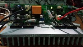
I have also used ceramic MLCC caps for the miller compensations , they are NPO/1206/100pf/100v.... one thing i did notice is when i changed over from MJE15035 in the Vas section to the BCP part i had to increase the C4 to 200pf to make the amp stable may be due the higher FT of BCP series...& regarding the LTP section i think SOT-23 package will too small some thing SOT-89 package might be more suitable...Valery ...statistics about BC 845-6 especially in Creek and Roksan are horrible though never measured how hard they push them there as an LTP but its a very common failure in these specific amps
In some of them we replaced the SMD parts with discrete and after that we had no more problems .
As about the OP and his pcb design we once more have to say that CFP like the P3a will be a tiny bit more sensitive when it comes to pcb design ...small details there might cause issues ...proximity for example especially in the VAS area might create both capacitance and inductance with often catastrophic results .
Farther more one thing that is overlooked by many is miller compensation I dont think that ceramic SMD is suitable for such an application both from aspects of voltage and general behavior as a part .
Kind regards
Sakis
I have also used ceramic MLCC caps for the miller compensations , they are NPO/1206/100pf/100v....
100V rated cap used as Miller compensation may be on the risky side for +/-55v rails. 0805 100pF 500V C0G MLCC costs only pennies.
100p/500v
Thanks for pointing that out.. I will surely use 250V or higher ...And I am not planning on using the amp on +-55V rails ... I plan on using them some where in the range of 40-45V max...
Cool 😎 Congratulations!
Does it drive the woofer well enough?
Thanks again ... Nope didn't test that part still...Had some other work to complete first ...Will test tommorow... Will post all test results.. on sine and sqaure waves ...
One more thing why is important to check on sqaure waves .... We are never meant to play square waves in real life ... I do understand the stability part but why else ??
Square wave is a combination of sine waves in wide range of frequencies (see Fast Fourier Transform for more theory on this).
Checking the square wave response, you can:
- measure the slew rate (low slew rate may cause significant distortion increase below certain point);
- see the step response quality (overshoot / undershoot) - especially useful at 10-20KHz;
- see if there's no ringing close to the fronts - ringing leads to sound quality degradation;
- briefly assess the bandwidth of the amplifier (having some experience);
- sees if the rase / fall times (slopes) are symmetric.
Last edited:
Valery ...statistics about BC 845-6 especially in Creek and Roksan are horrible though never measured how hard they push them there as an LTP but its a very common failure in these specific amps
In some of them we replaced the SMD parts with discrete and after that we had no more problems .
As about the OP and his pcb design we once more have to say that CFP like the P3a will be a tiny bit more sensitive when it comes to pcb design ...small details there might cause issues ...proximity for example especially in the VAS area might create both capacitance and inductance with often catastrophic results .
Farther more one thing that is overlooked by many is miller compensation I dont think that ceramic SMD is suitable for such an application both from aspects of voltage and general behavior as a part .
Kind regards
Sakis
Sakis, this is an interesting observation - I'll take a note and see how it goes.
I'm using BC 845-6 in a number of high-quality front-end designs, including the duals (pnp+pnp, npn+npn, npn+pnp). They all run fine so far, however I definitely don't have such a good statistic info, as you do.
Well, I'm using them only in low-voltage / low-current applications (like 15V / 2mA), never exceeding 30mW dissipation. Hopefully they survive in these conditions 🙂
Cheers,
Valery
Who makes the bc 845-6?
I can't find it in the NXP directory.
I did find the bc847bvn which is a dual PNPNPN in 6 pin package.
I can't find it in the NXP directory.
I did find the bc847bvn which is a dual PNPNPN in 6 pin package.
Mouser offer many options, for example:
http://www2.mouser.com/_/?Keyword=BC846B
On Semi, Diodes, Nexperia, Fairchild...
http://www2.mouser.com/_/?Keyword=BC846B
On Semi, Diodes, Nexperia, Fairchild...
I found one dual PNPNPN in that Mouser list
BC846BPDW1T1G
But it's bc846
Is bc845 a typo?
Ah! Right - sorry, that's definitely a typo.
The other one is BC856 with different characters in the end.
- Status
- Not open for further replies.
- Home
- Amplifiers
- Solid State
- Correct location for VBE bias transistor on CFP output amplifier