Right, that was a typo in his post, that I have copy-pasted in my post later on. Danger of copy/paste 😉
does this calculation for the 0.33E resistor sound correct ..
consider 45V rails
Vsat - 3V for 2SC5200
Maximum Output RMS swing possible is = (45/1.414) - 3 = 28.82V
RMS current following through the 0.33E = 28.82/4E = 7.2A
So Voltage Drop on the 0.33E is = 7.2 X 0.33 = 2.376V
Power dissipation on the 0.33E = P = V X I = 2.376 X 7.2 = 17W ????
For music a 5W or may be a 7W resistor may suffice but if a sinewave is supposed to be played for any length of time this resistor will burn out , wont it .... ?
No, gladly. The dissipated power in the 0R33 resistor calculates to RMS output current by square, times 0.33, divided by 2 (as it only leads current half the cycle). So, in your example, and at a 4 ohms load, this is:
(28.82/4)² *0.33/2 = 8.5W
Best regards!
(28.82/4)² *0.33/2 = 8.5W
Best regards!
No, gladly. The dissipated power in the 0R33 resistor calculates to RMS output current by square, times 0.33, divided by 2 (as it only leads current half the cycle). So, in your example, and at a 4 ohms load, this is:
(28.82/4)² *0.33/2 = 8.5W
Best regards!
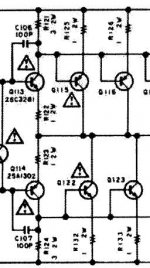
ahh understood , thank god i was going to order a 20W resistor but aint their a way to omit this resistor all together ... some like the attached schematic
Attachments
Resistors in the common collector leads are essential for thermal tracking and stability, as I've yet stated elsewhere in this board.
Best regards!
Best regards!
Resistors in the common collector leads are essential for thermal tracking and stability, as I've yet stated elsewhere in this board.
Best regards!
yes you are correct , i tried removing the resistor the bias just goes all over the place
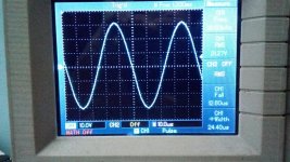
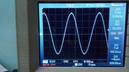
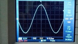
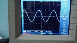
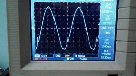
Sine wave test... Supply voltage 45NL loaded it comes down to 39-40VDC
Attachments
-
 IMG_20170215_000540-832x468.jpg126.2 KB · Views: 140
 -
 IMG_20170215_000623-832x468.jpg155 KB · Views: 136
 -
 IMG_20170215_000452-832x468.jpg126.8 KB · Views: 132
 -
 IMG_20170215_000534-832x468.jpg127.5 KB · Views: 132
 -
 IMG_20170215_000326-832x468.jpg124.5 KB · Views: 57
 -
 IMG_20170215_000422-832x468.jpg124.2 KB · Views: 50
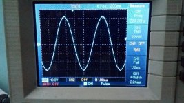
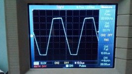
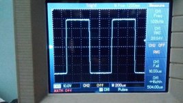
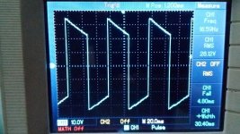
Square wave test.....I think I need to reduce the Miller compensation caps...May be then the lower and higher frequency graph will be a bit better... And load is 3.5E
Attachments

Resistors in the common collector leads are essential for thermal tracking and stability, as I've yet stated elsewhere in this board.
Best regards!
the emitter resistors are the feedback and it is they that stabilise the operating conditions.yes you are correct , i tried removing the resistor the bias just goes all over the place
does this calculation for the 0.33E resistor sound correct ..
consider 45V rails
Vsat - 3V for 2SC5200
Maximum Output RMS swing possible is = (45/1.414) - 3 = 28.82V
RMS current following through the 0.33E = 28.82/4E = 7.2A
So Voltage Drop on the 0.33E is = 7.2 X 0.33 = 2.376V
Power dissipation on the 0.33E = P = V X I = 2.376 X 7.2 = 17W ????
For music a 5W or may be a 7W resistor may suffice but if a sinewave is supposed to be played for any length of time this resistor will burn out , wont it .... ?
one pair of 150W devices operating from a loaded (already sagged due to high current delivery) is not enough for a reliable 100W into 8ohms output power. And certainly can't be used with a reactive 4ohms load.No, gladly. The dissipated power in the 0R33 resistor calculates to RMS output current by square, times 0.33, divided by 2 (as it only leads current half the cycle). So, in your example, and at a 4 ohms load, this is:
(28.82/4)² *0.33/2 = 8.5W
Best regards!
Assuming you stay with only one pair for an 8r0 dummy load:
output to load is 28.284Vac and 3.5355Aac (=100W into 8r0)
This current has to flow through the two emitter resistors on alternate half cycles, so we need to apply a 50% duty cycle.
Pdis = Iac^2 * 0r33 * 50% = 3.5355*3.5355*0.33*0.5 = 2.06W
5W 0r33 emitter resistor will get pretty warm during full power testing. And will drop over a volt so you need to increase your loaded supply rails by that volt.
However you are more likely to use a 2pair output stage.
The current through each resistor is now 1.77Aac and each has a Pdis of 0.52W and only drops <0.6V resulting in more maximum power from the same supply rail voltage.
For a 3pair output stage driving a 4r0 dummy load to a maximum output current of 7Aac (=196W into 4r0)
each emitter resistor passes 2.33Aac
Pdis = 2.33*2.33*0.33*0.5 = 0.9W
Last edited:
the emitter resistors are the feedback and it is they that stabilise the operating conditions.
Remember that the related design uses Sziklai pairs, where the related resistors are in the power devices' collector leads.
Best regards!
Pdis = Iac^2 * 0r33 * 50% = 3.5355*3.5355*0.33*0.5 2.06W
Remember that he was talking about 4 ohm loads instead of 8 ohm. So my calculation wasn't too bad, giving about four times the result as your's.
Using more pairs of output devices is another matter.
Best regards!
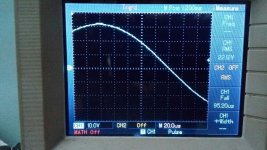
post88 pic2Square wave test.....I think I need to reduce the Miller compensation caps...May be then the lower and higher frequency graph will be a bit better... And load is 3.5E
the 103Hz square wave is showing a slope indicating that the bass is rolled off.
What is your target passband for this amplifier?
post88 pic2
the 103Hz square wave is showing a slope indicating that the bass is rolled off.
What is your target passband for this amplifier?
I want a flat frequency response from 10hz - 20khz ... I have noticed that when i increased the miller compensation capacitor for stability the frequency bandwidth gets skewed ... any thoughts ??
Attachments

I want a flat frequency response from 10hz - 20khz ...
Looking at post88 pic1: Target (in terms of LF rolloff) reached, I'd say.
Best regards!
From a commercial amp.
hi Michael , can you please provide the entire schematic or at-least tell the name of the product ...
Regards
- Status
- Not open for further replies.
- Home
- Amplifiers
- Solid State
- Correct location for VBE bias transistor on CFP output amplifier