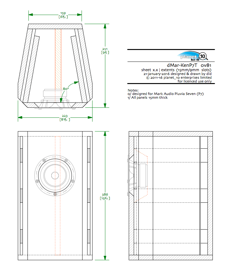
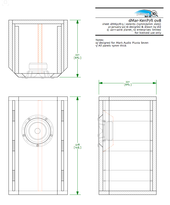
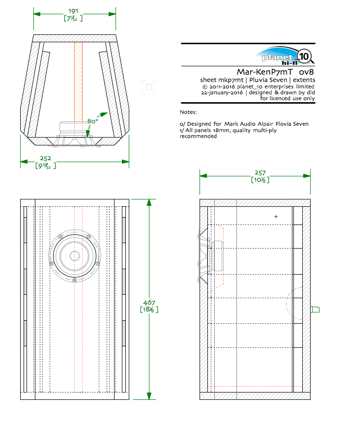
Poked by a member, i have started work on Mar-Kens for the new Mark Audio Pluvia Seven. Sketches below.
Drawings will be part of the CHR/CHP/CHN paid planset. I will need some beta builds thou. email me.
dave
Drawings will be part of the CHR/CHP/CHN paid planset. I will need some beta builds thou. email me.
dave
$hit, me and my big mouth, so now I gotta build a pair of these?😉
Probably too busy this weekend
So far, the only enclosure in which I can remember hearing this driver is in the FH3 - not quite on the same level as A7.3, but pretty damned fine - or did I say that already?
Probably too busy this weekend
So far, the only enclosure in which I can remember hearing this driver is in the FH3 - not quite on the same level as A7.3, but pretty damned fine - or did I say that already?
This is the 1st of the larger trapezoids. Bass with these should approach what the EL70 could/can do.
dave
dave
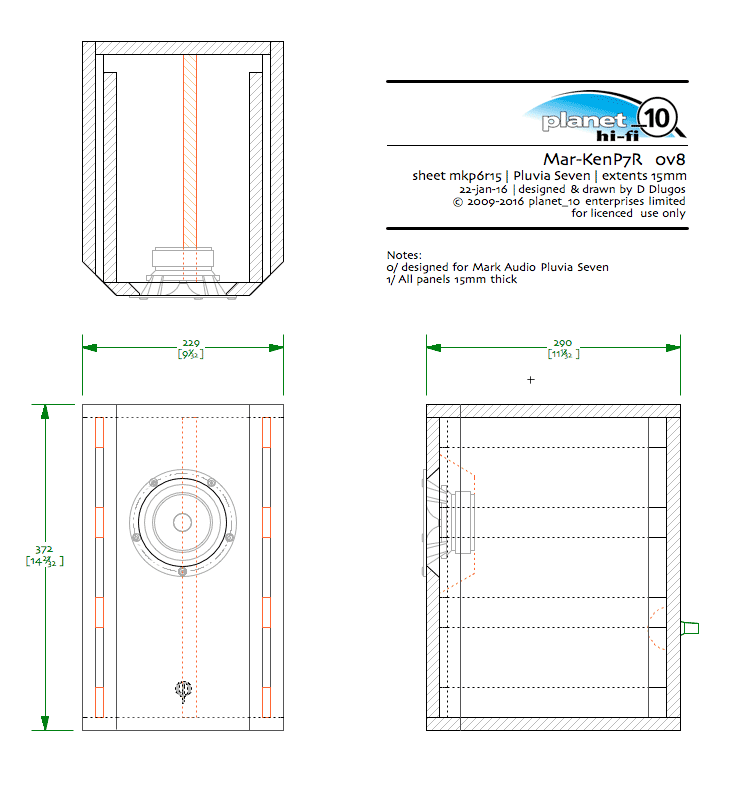
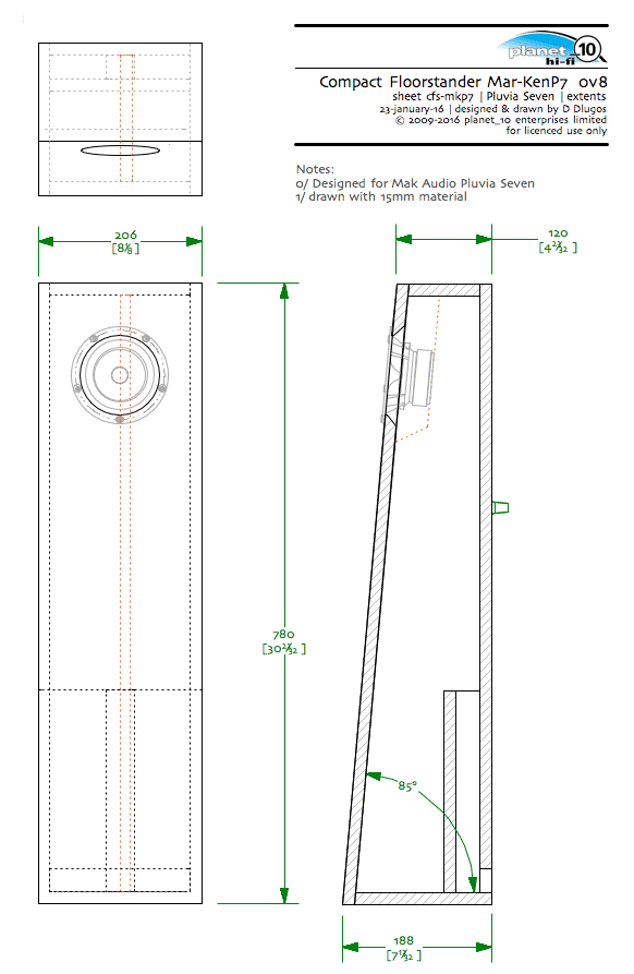
The CFS size shown can be fitted with EL70, A10.2, A10.3, A10p with suitable vent adjustment, and can be made wider for greater volume to fit A10p and FF165wk.
Chris has the larger A10p version in his HT.
dave
Chris has the larger A10p version in his HT.
dave
The CFS size shown can be fitted with EL70, A10.2, A10.3, A10p with suitable vent adjustment, and can be made wider for greater volume to fit A10p and FF165wk.
Chris has the larger A10p version in his HT.
I thought they looked familiar. Cunning plan to use that semi-modular design. 🙂
Dave...
How wide would they have to go for the FF165WK's?? Do you have a drawing made up??
Thanks!!
How wide would they have to go for the FF165WK's?? Do you have a drawing made up??
Thanks!!
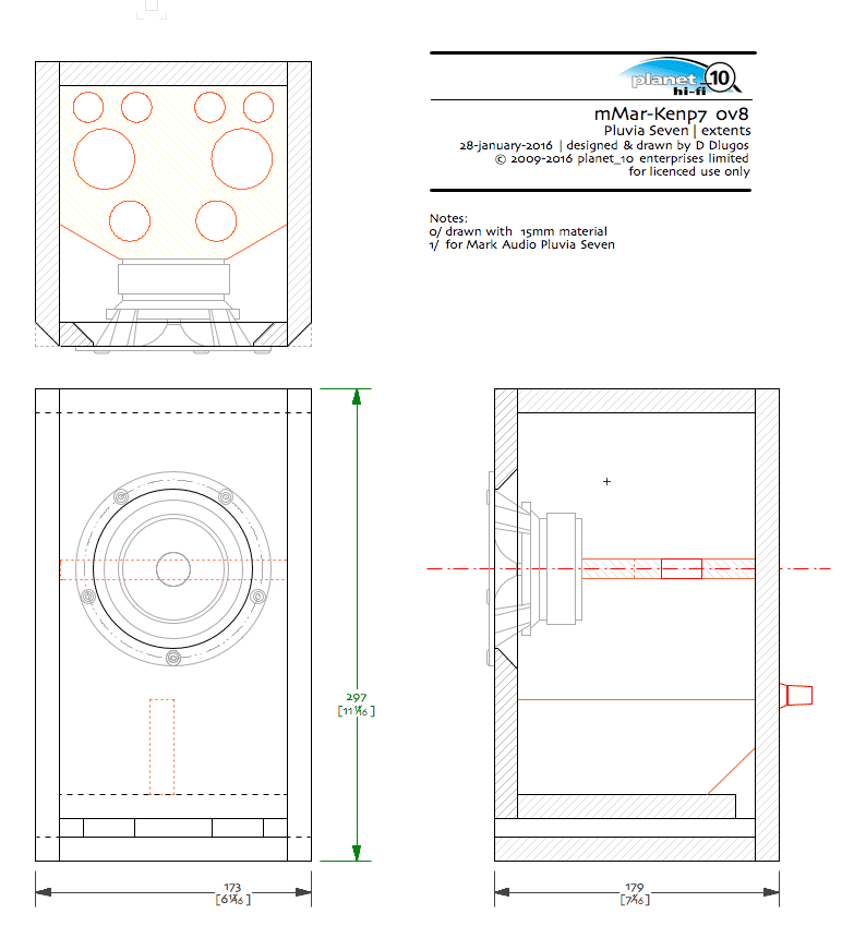
Hi Dave - how do you think the millisize mMar-KenP7 would go on its side as a centre channel?
Looking for something to complement my original dCHR-Ken70 (the first pair, if I recall correctly!) in a small HT setup, and it looks like the Pluvia 7 gets me something similar without needing to route a rebate this time!
Looking for something to complement my original dCHR-Ken70 (the first pair, if I recall correctly!) in a small HT setup, and it looks like the Pluvia 7 gets me something similar without needing to route a rebate this time!
This might sound silly but I wanted to ask how do you create the slots in the fonkens? Asking before I complete the build.
Which version?
If it's any of the designs with a group of tall/ skinny slots flanking the driver, there will be an internal panel on each side that forms the inside wall of the slots. The narrow width of those slots should be sized for port dividers to be cut from a standard thickness material - as I work in metric, I'll quote that those would likely be something like 9mm, 12mm, or on larger designs, even 15. Imperial measures would be (approx) 3/8, 1/2 or 5/8" .
I build the side panels as a sub-assembly - which including the spacers will be three layers.
- Secure two pieces of stock thicker than the three layers (2x4 stud works well for that) to the work surface in an L-shape to keep parts registered in place.
- Cut strips of material for the slot dividers the width of the spacing between the ports-(should be indicated on sketch)
Hint- if you dry fit the back panel to the rear registration guide, you can extend the port dividers to the back, the multiples of those strips will increase glue surface to the back panel - up to well over 1 sq in on some models, improve the integrity of that joint.
- Cut strips of scrap 3mm (1/8") MDF/ply as wide as the ports' height to serve as spacers for the glue up.
- Starting from one end, glue the divider blocks to the outside panel, then 1/8" spacer, block, space - etc. You can use a brad nailer/ stapler to speed that up a bit - but if panning to bevel the long front edges, be very careful - pins near the front edge can easily be in the path of the saw blade. I don't use pins, but rather use a blank panel, cauls, and clamps.
- don't rush - let the glue dry for at least a couple of hours before pulling clamps, but keep in registration blocks, along with the back panel.
- Apply the inside panel to the port dividers blocks, using a spacer between the inside edge and back panel still in registration block/ jig. As above, use a brad Pinner if you like, but still be careful with placement near front edge. Otherwise, clamp.
- I've only ever built bevel versions with side slots, so my next step is usually to make the first rough cut at the 45dg, - just make sure to cut the outside panel. No kidding - running near the end of a long day building a batch of 3 or 4 pairs of these, on one of the last panels to cut, I flipped it the wrong way on the saw- had to build one all new side wall.
" What did you learn in the shop today, Chris?"
So, now you're done with the ported side wall assemblies.
Last edited:
Thanks Chris!
Any chance there are pictures of how it all looks on the inside when it's finished? Either way, thanks a bunch.
Any chance there are pictures of how it all looks on the inside when it's finished? Either way, thanks a bunch.
Any chance there are pictures of how it all looks on the inside when it's finished?
Not sure if this will help, but here's a pic of my old Fonken build from 2006, based on Dave's original design for the FE127e. You can sort of see the vent spacers act as stops, and attachment points for the rear baffle.
jeff
Attachments

- Status
- Not open for further replies.
- Home
- More Vendors...
- Planet 10 hifi
- Mark Audio Pluvia Seven Mar-Ken Sketches