Better not because you will risk to approach instability when no additional source resistance will be there. Like when the pots are at max and the source is low Z or there isn't any source connected. Absolute minimum value has to do with interconnects, pots, and internal wiring inductance in each set up. 3.3k proved practically effective with all test builds in the various systems. Think of it as a gate stopper & RC filter component. But you can use >3.3k value, say up to 5k6, or use two of your 2k Shinkoh in series if you got four pieces by any chance.
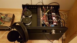
Testing as headphone amp. Headphones is philips fidelio x2. This is the best amp for its purpose I have ever heard/tested.
Many thanks to Salas and Tea-Bag for this opportunity.
Many thanks to Salas and Tea-Bag for this opportunity.
Attachments
Last edited:


Testing as headphone amp. Headphones is philips fidelio x2. This is the best amp for its purpose I have ever heard/tested.
Many thanks to Salas and Tea-Bag for this opportunity.
Looking good 🙂
I see an Raspberry as source on top picture left!; what DAC is feeding the DCG3 here?
Jesper.
That is a good sounding descrete r-2r dac from a fellow countryman of you 🙂
Soekris - dam1021 dac. Just using "raw" output.
The raspberry is connected using i2s direct with a reclocker in between. Great sound.
Soekris Engineering ApS, Products dam1021
Maybe it has been said before. What is the input and output impedance of the dcg3?
Soekris - dam1021 dac. Just using "raw" output.
The raspberry is connected using i2s direct with a reclocker in between. Great sound.
Soekris Engineering ApS, Products dam1021
Maybe it has been said before. What is the input and output impedance of the dcg3?
Last edited:
333k for naked input (the pot of choice ultimately determines that figure by paralleling it)
50R for line output
Near zero Ohm with jumpers or choice (Rz) for headphone output
50R for line output
Near zero Ohm with jumpers or choice (Rz) for headphone output
Salas, advice is needed. Could it work in simulation.
thanks.
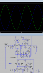
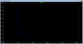
Apparently it can create opposite phases by simply connecting a source floating across two inputs. The 2nd harmonic will go higher than with normal SE in each phase and it can rely on a truly differential power amp to cancel it out. Blue & green traces are the outputs.
Attachments
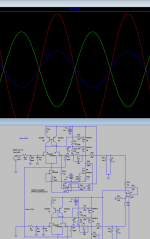
Since only transducers could be floating sources, when you don't want to use something like this http://www.mouser.com/ds/2/609/AD8476-877860.pdf for SE source to precision DIF, the two 499R can be lifted from GND and tied together while the second input is tied to GND. That would give equal to SE 2nd harmonic after a differential next (power) stage, not canceling due to pseudo balanced source input. Depicted with a differential op-amp next stage for simplicity while plotting the channels phase outputs and the red trace op-amp's recombination output.this similarly mean connecting the DCG3 R7 resistors to each other instead of to Ground in a balanced build?
thanks.
Some coax length with its shield on one end grounded could be used for connecting those resistors since there is enough physical distance between two channels.
Attachments
That is a good sounding descrete r-2r dac from a fellow countryman of you 🙂
Soekris - dam1021 dac. Just using "raw" output.
The raspberry is connected using i2s direct with a reclocker in between. Great sound.
Soekris Engineering ApS, Products dam1021
Maybe it has been said before. What is the input and output impedance of the dcg3?
Cool... R2R dac's are old fashion and very interessting 🙂 ...
Jesper.
Since only transducers could be floating sources, when you don't want to use something like this http://www.mouser.com/ds/2/609/AD8476-877860.pdf for SE source to precision DIF, the two 499R can be lifted from GND and tied together while the second input is tied to GND. That would give equal to SE 2nd harmonic after a differential next (power) stage, not canceling due to pseudo balanced source input. Depicted with a differential op-amp next stage for simplicity while plotting the channels phase outputs and the red trace op-amp's recombination output.
Some coax length with its shield on one end grounded could be used for connecting those resistors since there is enough physical distance between two channels.
Wow Salas that is great!
I had to read what you wrote three times before I think I understood.
So what you are saying, please correct me if I am wrong, is that the DCG3 bal which has two DCG3 gain blocks will do a SE to balanced output if the SE input + is connected to the +phase and the SE reference is connected to the _ phase but the H2 will be slightly higher.
Also, it will do SE to balanced output if the two R7 499r are connected to each other instead of to ground and the _phase input is grounded and the H2 is similar to the SE version of the DCG3.
Does it therefore make sense that in a balanced DCG3 build one should tie the two 499R's together irrespective of whether one is using a pure differential input from lets say a balanced DAC or a SE to balanced converter like the AD8476 or a SE source directly with _phase appropriately grounded. BTW the distance between the two R7's is only 42mm.
Thanks. nash
1) If you have a true balanced source (a floating transducer or differential DAC chip outputs like MagicBus/Kostas has) you need not do any mod. Only connect each phase to each channel. As he did. In that case any second harmonic in the phases nulls after recombination at a further differential stage's output (truly balanced symmetric power amp for instance) and the THD plot simulates as picture 1.
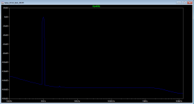
2) If you also have single ended (grounded to one side) source that you want to drive both phases channels from (pseudo balanced) you should connect the R7s together and ground the second channel's input as noted before. In that case after recombination in a further truly balanced stage the THD plot simulates as picture 2.
3) When connecting a truly differential source between channels inputs to the above configured (R7+R7) but with the second input not grounded you still get same simulated performance as picture 1. SE/BAL configuration switch or configuration jumper in the female XLRs will be needed when having both SE and BAL sources to choose from.
4) If you want to make an SE source behave like a truly balanced source your best bet is to use a special precision chip for such conversion jobs. So to potentially have the second harmonic null of picture 1 like Kostas was after. As much as it is possible by CMRR in a practical fully differential system (source to speaker).
But you may don't mind or like some low 2nd harmonic, also you may don't want more silicon in the way of your source signal. That way with an SE source and R7s connected + second input grounded you get picture 2 at best which is equivalent to using SE source and single DCG3 normal. Not too bad still (-112dBV 2H at 1kHz 1V output).
Attachments
Thank you Salas. Very clear explanation of simulation results.
Perhaps this will encourage others to build a bal version of the DCG3 since it affords so much flexibility and future proofing.
Perhaps this will encourage others to build a bal version of the DCG3 since it affords so much flexibility and future proofing.
A thing I forgot to mention is you can even use a special transformer like those Jensen still makes for SE to BAL instead of specialized op-amp chips. Older high quality mixing desks relied on such for their noise performance.
A thing I forgot to mention is you can even use a special transformer like those Jensen still makes for SE to BAL instead of specialized op-amp chips. Older high quality mixing desks relied on such for their noise performance.
Funny, you read my mind!
I'd like your opinion on these two approaches:
1)Unbalanced to balanced converter using a TI DRV134 or THAT1646. Such as
UBC01 Unbalanced to balanced driver - Sjöström Audio
I like this one over the ebay ones because it is one board for each channel and also has a regulated power supply on the same board. Option for LM317/337 or discrete as you wish.
For power supply to these circuits what is more important, low noise or regulation or both? Is this board worth considering? If I am doing this I would like to do the best I can.
2)Using a transformer Jensen JT11P1 to convert unbalanced to balanced, such as the right side circuit
http://www.jensen-transformers.com/wp-content/uploads/2014/08/as060.pdf
I also like this approach because no worries of noise interactions, simplicity.
Could you please share your opinions on each approach especially given the recent discussion on H2. Eager to learn.
Thanks. nash
Last edited:
1) Low noise and no ground loops are important
2) Small loop area, no more power trafo & psus or many extra silicon junctions, elegant
2) Small loop area, no more power trafo & psus or many extra silicon junctions, elegant
1) Low noise and no ground loops are important
2) Small loop area, no more power trafo & psus or many extra silicon junctions, elegant
Looks like you are leaning towards the trafos. Right?
The top quality chips could bring less measurable distortion in high voltage pro sound signals and more bandwidth but for home hi-fi maybe simpler is better especially about solving potentially new integration problems of introducing extra active circuits in a busy diy build.
- Home
- Source & Line
- Analog Line Level
- Salas DCG3 preamp (line & headphone)