Does this mean that BA3 PCB has +phase/GND/-phase inputs or is it two indepented boards with hot and ground one used for positive and the other for negative phase? Could you post a diagram of your circuit?
http://www.diyaudio.com/forums/pass-labs/201281-burning-amp-ba-3b-balanced.html
"Note that the two input Source load resistors have
been combined instead of going to ground."
I dont know whether this connection is what enables it to perform like a unbalanced to balanced converter. My understanding reading Pass was that this is SUSY which results in lowered distortion.
Speaking as an novice would this similarly mean connecting the DCG3 R7 resistors to each other instead of to Ground in a balanced build? They are after all connected to each other thru PCB Ground. Salas, advice is needed. Could it work in simulation.
thanks.
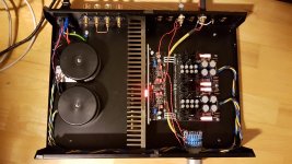
Yes it is ok...P.S. I see a rather deep soldering iron wound on left hand C5. Did you try verify its still OK?
Was slippy for a tenth of a second there.
Actually this Holfi has an alu faceplate.
Like this
http://i.ebayimg.com/images/g/dLIAAOSwpdpVbW9f/s-l400.jpg
Also have an Integra 88se elswhere with that wood faceplate. Plays allright.
That explains everything. This BA3 version has balanced input thus working the way you report. DCG3 doesn't have this topology. I don't know if it could be done but I need to repeat that I don't need this function. It would be good to know thoughhttp://www.diyaudio.com/forums/pass-labs/201281-burning-amp-ba-3b-balanced.html
"Note that the two input Source load resistors have
been combined instead of going to ground."
I dont know whether this connection is what enables it to perform like a unbalanced to balanced converter. My understanding reading Pass was that this is SUSY which results in lowered distortion.
Speaking as an novice would this similarly mean connecting the DCG3 R7 resistors to each other instead of to Ground in a balanced build? They are after all connected to each other thru PCB Ground. Salas, advice is needed. Could it work in simulation.
thanks.
Just to add to my previous post 1261 please refer to post #27 by Nelson Pass in BA3b article
"Would you not want to be able to drive it with single-ended input?
So it is this connection that does the trick.
So how can we make the DCG3 convert SE to balanced?
"Would you not want to be able to drive it with single-ended input?
So it is this connection that does the trick.
So how can we make the DCG3 convert SE to balanced?
One typical thing done is to reverse the SE input signal with a unity gain op-amp and create an opposite phase copy to drive the other half.
About alternatively modding the SE channels to lift and tie together the R7 feedback resistors I would have to create a doubled up simulation to confirm there will be no adverse effects. Which is not something done in a moment. I would have to have time.
About alternatively modding the SE channels to lift and tie together the R7 feedback resistors I would have to create a doubled up simulation to confirm there will be no adverse effects. Which is not something done in a moment. I would have to have time.
A nice package from Modushop arrived this morning; so time to get busy with the drill press and get this boxed up. I shall miss the plank though😉
One typical thing done is to reverse the SE input signal with a unity gain op-amp and create an opposite phase copy to drive the other half.
About alternatively modding the SE channels to lift and tie together the R7 feedback resistors I would have to create a doubled up simulation to confirm there will be no adverse effects. Which is not something done in a moment. I would have to have time.
Thank you Salas for even considering the simulation. Time a plenty.
I can only state that in my subjective opinion and reflecting those of the very few I know who have gone the balanced route with the BA3, the bal version sounds better. It would be great if a relatively simple connection or two could do this. In the meanwhile I plan on continuing with my DCG3bal build.
MagicBus/Kostas could you share your listening impressions using your build in SE(half the build) vs. balanced?
nash
I' ve spent most of the weekend listening to balanced mode... I just confirmed that SE mode works flawlessly and without hum. I' ll have more listening in different configuration during next days!
A nice package from Modushop arrived this morning; so time to get busy with the drill press and get this boxed up. I shall miss the plank though😉
Tonewood magic may evaporate 😀
Prelimanary volume pot (25k - ladder attenuator ebay style 😀 ) and prelimanary cabling for testing purpose. In the office setup for testing... line out.. this preamp has potential. 😀
Too early to make serious listening.. will try in a week or so in my main setup..
Now in the home office. Dac-dcg3-audio note soro integrated (have for repair)-dali 350 speakers..
I was settling for approx 150ma bias (30 ohms headphones) using the 7.5r (from tea-bag GB) for r10. I got about 160ma.. Good heatsinking.. Is 160ma ok?
Regarding dc offset. I really didnt notice any improvent with or without the opamp. Opamp is in now when playing. Approx +-1mv offset. Will calibrate again in some days..
Any ideas for optimum grounding scheme? I had non connection between the lineboard and chassis ground so I mounted a small cable strip from line in to chassis gnd - pot is grounded. Works ok.
Attachments

Last edited:
For that kind of big sink in your pictures 160mA is easy work, no need to hold its bias back.Prelimanary volume pot (25k - ladder attenuator ebay style 😀 ) and prelimanary cabling for testing purpose. In the office setup for testing... line out.. this preamp has potential. 😀
Too early to make serious listening.. will try in a week or so in my main setup..
Now in the home office. Dac-dcg3-audio note soro integrated (have for repair)-dali 350 speakers..
I was settling for approx 150ma bias (30 ohms headphones) using the 7.5r (from tea-bag GB) for r10. I got about 160ma.. Good heatsinking.. Is 160ma ok?
Regarding dc offset. I really didnt notice any improvent with or without the opamp. Opamp is in now when playing. Approx +-1mv offset. Will calibrate again in some days..
Any ideas for optimum grounding scheme? I had non connection between the lineboard and chassis ground so I mounted a small cable strip from line in to chassis gnd - pot is grounded. Works ok.
As I wrote before this preamp may give steady low offset result on its own before servo -especially when on a big sink- but the opamp is your safeguard because drifts can happen at a later point when put in a system and not looking for them anymore. Unless the power amp has an input coupling capacitor, to leave the opamp out is still a future DC risk.
As for grounding, when its silent in your own way, you are done. Line-in RCA ring and a wire to chassis isn't much different than a wire from pot's common to chassis that we usually do anyway.
I found two of these toroids lying around (220v/18v 15VA +18v 15VA) and was thinking that maybe I could parallel each one of them and use them for the DCG3. Would that be OK, or am I making things too convenient for me...?
https://www.dropbox.com/s/urd2p04c763cftp/Foto 2017-01-31 13 45 44.jpg?dl=0
I hooked them up and got around 22,35V. I guess that could be a bit too much?
//Ronny
https://www.dropbox.com/s/urd2p04c763cftp/Foto 2017-01-31 13 45 44.jpg?dl=0
I hooked them up and got around 22,35V. I guess that could be a bit too much?
//Ronny
They would normally show less ACV when well loaded. Else they are not in good tolerance for nominal voltage standards.
Even if you parallel two you will have just one 30VA+30VA=60VA total.
In my opinion do it double mono with those if you must use them but you will have to stay at 100mA bias for those toroids to be working at about 35-40C each prolonged.
Even if you parallel two you will have just one 30VA+30VA=60VA total.
In my opinion do it double mono with those if you must use them but you will have to stay at 100mA bias for those toroids to be working at about 35-40C each prolonged.
18Vac has a peak voltage of 25.46Vpk
your measured 22.35Vdc seems far too low.
Output voltage = mains voltage / rated primary voltage * rated secondary voltage * (1+transformer regulation)
if your 36VA transformer has a regulation value of 12% and you have a mains voltage of 225Vac
then your 220:18Vac transformer will give 225/220*18*1.12 = 20.6Vac
convert thatto peak and you get 29.16Vpk
Subtract 0.5V for the diode drop and you should have ~28.6Vdc across the smoothing capacitor. Attach a load and the PSU voltage will droop.
They would normally show less ACV when well loaded. Else they are not in good tolerance for nominal voltage standards.
Even if you parallel two you will have just one 30VA+30VA=60VA total.
In my opinion do it double mono with those if you must use them but you will have to stay at 100mA bias for those toroids to be working at about 35-40C each prolonged.
each secondary winding will have a maximum continuous output of 15VA/18Vac = 0.833Aac220v/18v 15VA +18v 15VA
After de-rating for a capacitor input filter you end up with a maximum continuous DC current of ~450mAdc
To run the transformer cooler I suggest you use <=50% of that maximum continuous rating i.e. continuous current <=225mAdc from each secondary winding.
He measured the secondaries with an ACV RMS meter most probably. That's what I understood.18Vac has a peak voltage of 25.46Vpk
your measured 22.35Vdc seems far too low.
18Vac has a peak voltage of 25.46Vpk
your measured 22.35Vdc seems far too low.
Output voltage = mains voltage / rated primary voltage * rated secondary voltage * (1+transformer regulation)
if your 36VA transformer has a regulation value of 12% and you have a mains voltage of 225Vac
then your 220:18Vac transformer will give 225/220*18*1.12 = 20.6Vac
convert thatto peak and you get 29.16Vpk
Subtract 0.5V for the diode drop and you should have ~28.6Vdc across the smoothing capacitor. Attach a load and the PSU voltage will droop.
As I said his measured voltage seems to be far too low.He measured the secondaries with an ACV RMS meter most probably. That's what I understood.
Maybe they are mislabelled and should be 15Vac secondaries. Or the battery in his DMM needs changing, or he forgot to attach the smoothing capacitor?
But even a 15Vac 30VA transformer will give more than 22.35Vdc after rectifying and smoothing.
Last edited:
Thanks for your help!
Yes, I just connected them to mains and meassured directly with a volt meter, and got 22,35Vac.
I also had another one: 220v/18v+18v+8v/77VA. But that's a bit on the small side too then i guess.
Considering other costs, and time spent, I might as well order a proper one.
Thanks again!
//Ronny
Yes, I just connected them to mains and meassured directly with a volt meter, and got 22,35Vac.
I also had another one: 220v/18v+18v+8v/77VA. But that's a bit on the small side too then i guess.
Considering other costs, and time spent, I might as well order a proper one.
Thanks again!
//Ronny
Thanks for your help!
Yes, I just connected them to mains and meassured directly with a volt meter, and got 22,35Vac.
I also had another one: 220v/18v+18v+8v/77VA. But that's a bit on the small side too then i guess.
Considering other costs, and time spent, I might as well order a proper one.
Thanks again!
//Ronny
ask a friend to check your DMM against theirs.I hooked them up and got around 22,35V.
- Home
- Source & Line
- Analog Line Level
- Salas DCG3 preamp (line & headphone)