![WP_20170124_014[1].jpg](/community/data/attachments/537/537028-ed227d4789c0b2a920ac81aed94dac0f.jpg?hash=7SJ9R4nAsq)
Why not use LED bias on the cathode instead?
I haven't used battery bias, but isn't it supposed to be between the grid and ground, with a input cap before the battery...?
Agreed, would put the battery out of audio path.

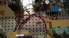
The 2.2uF film cap of heaters regulator is connected to signal ground and to SLB, this can be cause the ground loop?
Fixed, was the cable connecting the signal ground to SLB (safety loop breaker).
Attachments
![WP_20170124_015[1].jpg](/community/data/attachments/537/537115-98c779a1db76d84ab7f3632e64573330.jpg?hash=mMd5odt22E)

Why not use LED bias on the cathode instead?
I haven't used battery bias, but isn't it supposed to be between the grid and ground, with a input cap before the battery...?
Agreed, would put the battery out of audio path.
What's the advantage?
Hello,
During the modification of my amplifier I have shorted the output 200V S/F+ to the ground today and the resistor R1 burned. Can you tell me, what parts were damaged? I have to change burned R1 and probably Q1. What about Q2, D1, D2? Are they also damaged?
Should I also change for new Q3 and Q4, Q5? Maybe others?
Your help would be appreciated.
R1 Q1 are usually the victims, sometimes along Q4 or Q5, Q6, D3. Q3 not so often. There is also a safe troubleshooting example case link in post #1. If you will use a heavy duty Schottky diode for D3 you may prevent damage from further such shorting accidents. Replace D1, D2, with common diodes even if handier than specific Zeners in your stash as you are at it just in case they got a hit.
Salas I'm repairing a damaged SSHV2, tested all semis with Atlas DCA55 and changed the damageds but not work properly, red LED lights and voltage only can go between 175VDC & 185VDC, measured CCS and is 39mA, my target is 150V 30mA for 26 preamp.
![WP_20170217_005[1].jpg](/community/data/attachments/559/559969-c1579c35d2f4b56995fe43d5fcb4041f.jpg?hash=wVecNdL0tW)
I never suspected in this culprit.
That's an alternative to the single Zener position for protecting other surrounding parts not only during start up but also in case of an accidental output short. Did it go on a short?
The CCS is not working, I isolated the CCS desoldering C1 leg to R6, IRF840 and R6 the leg connected to F+, red LED lights but Q4 or near a little of smoke, that's with attached 4K7 dummy load.
Change the kelvin 4 wire to F+ & F0 to the dummy load, CCS fix to 396mA aprox. can't change the CCS with R4 trimmer. Measured D1 & D2 and seems broken I will desolder and measure.
CCS max reach 26mA with dummy load 4K7 connected to F+ & F0, voltage across 4K7 110-120V jumping not fixed Vout.
- Home
- Amplifiers
- Power Supplies
- Simplistic mosFET HV Shunt Regs