Keeping in mind, that all 3 (3116/18/28) have the same OC-Trippoint (7.5A) i should go for the 3128. With its reduced RDSon of 90mR (compared to 120mR) it should handle even higher output power.
With a peak power of 6A in PBTL there will be 36A^2*90mR (ideally 90+90 parallel) = 3.25W to dissipate.
(Of course, this is not working for continuous output power as RDSon increases by factor 2-3 without adequate "cooling")
With a peak power of 6A in PBTL there will be 36A^2*90mR (ideally 90+90 parallel) = 3.25W to dissipate.
(Of course, this is not working for continuous output power as RDSon increases by factor 2-3 without adequate "cooling")
Some distances in pic still to 0mm because reshaping traces. I didn't look at minimum distances Elecrow/Itead earlier, so I had to change the 0.2 vias to 0.3+0.15 ring, and that causes me some thinking 🙂
3128 also has slighly longer startuptime and lower gvdd voltage.
Temperature isn't problem for me on gmarsh or Sanwu, I have groundpins connected to outputside also and more copper than Sanwu, so temperature should be lower than Sanwu.
Temperature isn't problem for me on gmarsh or Sanwu, I have groundpins connected to outputside also and more copper than Sanwu, so temperature should be lower than Sanwu.
Just different than 3116/18. Start up time also not likely to affect temperature, but might affect pop ?
Hi, I brought TPA3116 2*100Watts on the other day, So i have problem with.
1. Left channel has 1 Volt DC offset, It's make speaker push forward and voice coil generate heat, Yet sound also good.
2. Right channel's inductor heat than left channel, Yet sound also good.
What problem is?, or i just bad luck.
Sorry for poor english and thank you.]
Ground the inputs and put a load on the outputs and measure again.
I saw little speakers in picture. Right channel probably switches at around 100kHz, that might be the heat you noticed in that channel inductors, you can set meter to Freq and check.
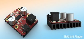
No TPA3118, but TPA3116. -> Flipped -> Heatsink on the bottom.
What's the difference between the tpa3118 and a flipped tpa3116?
What's the difference between the tpa3118 and a flipped tpa3116?
"Flipped" may be accurate but confusing to some. The 3116 chip has its heat sink pad on top. This allows a heat sink to be mounted to the chip. The 3118 is the same chip electronically, but it's heat sink pad is on the bottom and thus it's "heat sink" is the copper ground planes on the PCB (physically wave soldered). On a multi-layer board, the heat sink on the bottom, is connected to all the PCB ground planes - directly touching the chip and lower levels via thru holes. In this configuration, the 311x is rated at only 2x30w, a thermal dissipation limitation. See the pic

😀 So the tpa3118 is more powerfull than tpa3116, 2x30w 8 ohm is 2x60w 4 ohm, and tpa3116 is just 2x50w. Yes they are both thermally limited.
It's the same silicon, just thermal pad size and position differs. Mounting it flipped through board makes the thermal pad available on the back side of the board, so no need to waste space on top.
Cost 3128 ampboards isn't higher than Sanwu pbtl's, considering the electrolytics/inductors I replace and terminals added. And then there should be some benefit from higher rated resistors and capacitors alone for durability, ignoring the tpachip's uncertainty 🙂 The filmcaps on differential input is a nice feeling too 🙂 Curious if it will work ok 😀
You can mount it in a very tiny aluminium Hammond/Fisher boxIt's the same silicon, just thermal pad size and position differs. Mounting it flipped through board makes the thermal pad available on the back side of the board, so no need to waste space on top.
16mm maybe
http://www.produktinfo.conrad.com/datenblaetter/1300000-1399999/001369496-da-01-de-ALU_GEH_NATUR_ELOXIERT_AKG_55_16_50_ME.pdf
Last edited:
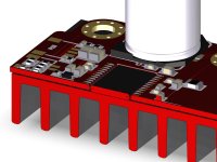
Sorry to be dense... but are you actually going to have a big hole in your pcb so the flipped tpa3116's thermal pad is directly exposed for the heatsink?It's the same silicon, just thermal pad size and position differs. Mounting it flipped through board makes the thermal pad available on the back side of the board, so no need to waste space on top.
I guess I still don't understand how a flipped tpa3116 is different than a tpa3118 (except for pin orientation).
Maybe another way to ask the question: what do you achieve by flipping the tpa3116 that is not done naturally by the 3118?
Sorry to be dense... but are you actually going to have a big hole in your pcb so the flipped tpa3116's thermal pad is directly exposed for the heatsink?
Correct, so you can have a "bigger heatsink" on the powerpad than when mounting it the "right" way.
Maybe another way to ask the question: what do you achieve by flipping the tpa3116 that is not done naturally by the 3118?
You skip the PCB as thermal resistor (or heat path) compared to a TPA3118.
3116: Rth_junction_case (top) + Rth_paste + Rth_heatsink
3118: Rth_junction_case (bottom) + Rth_solder + Rth_pcb ( + Rth_paste + Rth_heatsink)
When you moun the heatsink onm top, you're somewhat limited in size due to the bulk caps which should be mounted in short distance.
This was the initial idea. In theory, doing so increases the continuous output power duration until thermal shutdown.
Like so:

Cut in half:

Cut in half:
Attachments
Last edited:
When you moun the heatsink onm top, you're somewhat limited in size due to the bulk caps which should be mounted in short distance.
This was the initial idea. In theory, doing so increases the continuous output power duration until thermal shutdown.
OK, now I get it. So you could in theory get away with a tpa3118 as long as your heatsink had a "shim" on it that was the same thickness as your PCB... which likely requires a custom heatsink and/or machining, so flipping the 3116 is easier. Although you are also banking on the thickness of the PCB being the same as the mounting depth created by the chip pins.
Definitely a cool idea (in both the figurative and literal sense of the word). But I seem to recall Gmarsh said he tested thermals with the 3118 on his Wiener board. If memory serves, didn't he push a sine wave through at max voltage to a low-ohm power resistor? He uses a thermal pad to couple the PCB to the chassis. Obviously direct-connect of a heatsink will be better than having intermediate layers of PCB and thermal pad; but if the latter is good enough... Granted, that's all from memory, which isn't the best. 🙂 I'll look and see if I can find where he talked about that. Also, your PCB is much smaller than the Wiener PCB, so the "heatsink" (i.e. PCB ground plane) is smaller.
If you open some older CD-Roms, you may see this kinda mounting quite often. Also in older portable audio gear, like cassette or cd players. Mainly because saving packaging height.
When using the 3118/3128, the chip isn't mounted flipped, so having the pcb in between the ICs bottom side power pad and the heatsink.
I actually dropped the flipping idea because the newer 3128 has lower on-resistance.
In burst mode, all chips are putting out nearly the same amount of power, until they shutdown due to overtemp. This highly depends on the thermal mass connected to the pad and it's heat transfer resistance. The flipper should win on the long run, but generates more heat than the newer 3128.
Last edited:
- Home
- Amplifiers
- Class D
- TPA3116D2 Amp