Should work fine. I have a delay circuit in another amp that called for 10v and Inusef 8.1v. Works fine.

DCSTB AC input?
I have two of the same multi-tapped transformers (found another one!) with secondary winding's of: 0v-9v-12v-15v-18v-21v-24v-30v
Each DCSTB requires an AC input of AC-CT-AC.
I'm not sure: Using my transformers, should I use the following taps for AC-CT-AC: 0v-9v-18v?
Thanks
I have two of the same multi-tapped transformers (found another one!) with secondary winding's of: 0v-9v-12v-15v-18v-21v-24v-30v
Each DCSTB requires an AC input of AC-CT-AC.
I'm not sure: Using my transformers, should I use the following taps for AC-CT-AC: 0v-9v-18v?
Thanks
Measure with AC meter across the taps but I think the most it can give you is 15-0-15 differences by utilizing the 0-15-30
It sims better without the opamp..... can it be used without ?
I advise against because it will eventually drift in use and such a decision will be a dangerous risk to any DC input coupled power amp system.
But I don't see any really worthwhile difference when simulating with an OP07 and my original file vs yours. In measuring practice I have only seen the TL082 chip adding to the noise floor and to the THD. All others I had were virtually innocuous for those two aspects.
Attachments
OK, thanks.
Just to get it going how about I use just one DCSTB board and feed the AC-CT-AC with both of my transformers so:
18v tap - 0v tap // 0v tap- 18v tap
Thanks
Just to get it going how about I use just one DCSTB board and feed the AC-CT-AC with both of my transformers so:
18v tap - 0v tap // 0v tap- 18v tap
Thanks
Measure with AC meter across the taps but I think the most it can give you is 15-0-15 differences by utilizing the 0-15-30
Sorry fot transformer theory 101 questions but if both transformers connected correctly a voltmeter across AC-AC I should get 36v?
In theory, yes. Provided you get the phase correct.
I got the Focusrite Scarlett Solo audio interface and it does appear to let me turn the volume pot to max level and not have a crazy exploding FFT. I still have the 15k R1 in place so maybe the harmonic profile is not perfect but THD is now 0.0055% much lower. However, I see all sorts of lower frequency peaks appearing now. The amp appears to be behaving though and the clean FFT confirms why my ears were not hearing anything when the UCA202 was showing high levels. The measured frequency response is now ruler flat.
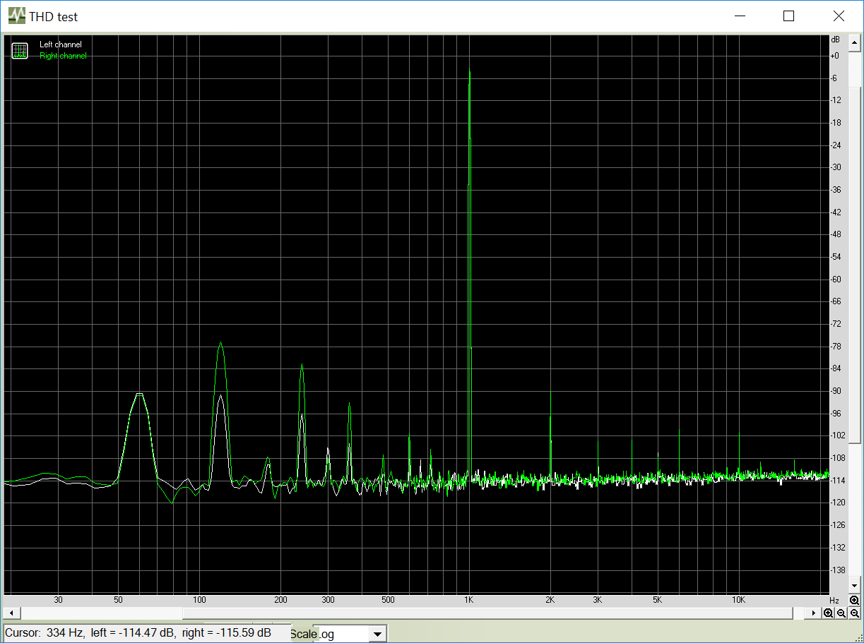
The left channel is going through a microphone amp on the Solo and the right channel is going through a line amp, with gains adjusted to match but it looks like they have different low frequency pickup of noise artifacts.
The left channel is going through a microphone amp on the Solo and the right channel is going through a line amp, with gains adjusted to match but it looks like they have different low frequency pickup of noise artifacts.
Attachments

Last edited:
That's very encouraging. Seems that most of your troubles were experimentally related. You may have a ground loop in your new rig now though. Is there a ground lift switch in the Focusrite? Set your FFT at 24 Bit 48K in Arta and 65536 long the least because you still get the same -114dB floor limit like before and the new one must be more capable. Run an interface own loop test to establish what is inherent and what is added so to debug DUT grounding / cabling better.
P.S. The operating system device driver must be set at 24/48 also
P.S. The operating system device driver must be set at 24/48 also
Salas, I have a question.
I just got my example up and running. I let it warm up 15 minutes or so without the op-amp and adjusted the offset to as close to zero as I could get it...easy process.
After installing the op-amp, I expected the offset to hover around a millivolt or so.
Instead it drifts from 0V to 3mV or so.
Is that normal?
I got all the matched transistors and NECs from Tea.
It produces sound and quite good sound I might add. I'm only using it as a line stage.
It could be noise in the DMM. I see +/- 0.5mV max with a Fluke 87V in mine. It could be to 1mV because of op-amp sample but 3mV I have seen with BJT input chips only. Stick a TL072 or an OPA2134 to see if its the op-amp indeed. Does it move the screen line at all if you will connect its output to the oscilloscope and set say 5mV/div sensitivity?
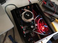
It lives. I gotta see how hot it gets. It's a pretty tight fit.
Listening impressions to come in a few days.
🙂
Stick a TL072 or an OPA2134 to see if its the op-amp indeed. Does it move the screen line at all if you will connect its output to the oscilloscope and set say 5mV/div sensitivity?
I don't have a oscilloscope.
Must be something to do with the op-amp I have.
I stuck a OPA2134PA in the socket and now offset varies between .1-.2mV...much lower.
Tea, are you including Chinese counterfeit AD823s in your kits?😀
Its half the BW and less slew rate op-amp than the AD but its inherent offset and sample by sample behavior are the more affecting parameters in this. A friend of mine could not hear small differences between good resulting servo op-amps on loudspeakers with this preamp, Tham though said he could. I think I can hear little tonal differences on headphones mainly. Can you hear any in this chips switch?
- Home
- Source & Line
- Analog Line Level
- Salas DCG3 preamp (line & headphone)