no that didn`t workout as im still getting a squarewave inthe output with posive peak 36nV and lower peak at -4nV with a little bit of shootout at leading edge of the squarewave.
Tried simulating but im getting error as there are no lib files for the IR2110
Did t work?, I have get it working.
put smpsadd in sym directory and lib or sub in lib.
regards
Attachments
Last edited:
Did t work?, I have get it working.
put smpsadd in sym directory and lib or sub in lib.
regards
I tried that also but this time im getting this error.
Attachments

Make and test. Then will tell us.
Better use Microcap simulator than Ltspice - for audioapplications its more native.
Better use Microcap simulator than Ltspice - for audioapplications its more native.
Last edited:
Ltspice is free and quite executed many schematic with ease. I dont deny but Microcap is a bit expensive.Make and test. Then will tell us.
Better use Microcap simulator than Ltspice - for audioapplications its more native.
If the IR2110 executes properly in LTspice then it should be fine. Again i need to manage new libraries for the Microcap and adapting to new software takes some time as well.
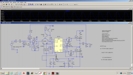
im getting this output now what is wrong in here
You dont have gate driver supply voltage in the scematic at all.
do i need to short 9 and 13? add supply of 12V for 9leg?
I have used this circuit
http://www.diyaudio.com/forums/atta...atts-1200-watts-using-2-mosfets-amplid300.png
I have used this circuit
http://www.diyaudio.com/forums/atta...atts-1200-watts-using-2-mosfets-amplid300.png
Last edited:
do i need to short 9 and 13? add supply of 12V for 9leg?
I have used this circuit
http://www.diyaudio.com/forums/atta...atts-1200-watts-using-2-mosfets-amplid300.png
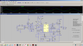
You shorted pin 9 and 13. Do not short them! And tie 12V to pin-9!
Your schematic was good earlyer in this aspect. Restore it!
Your schematic is actually dimensioned better than the original which was explosive.
You shorted pin 9 and 13. Do not short them! And tie 12V to pin-9!
Your schematic was good earlyer in this aspect. Restore it!
Your schematic is actually dimensioned better than the original which was explosive.
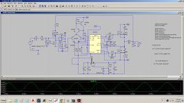
Pin 9 and 13 are connected through a cap and I have removed that cap and added +12V to the VDD but the output not as expected.
Attachments
Pin 9 and 13 are connected through a cap and I have removed that cap and added +12V to the VDD but the output not as expected.
No, they are still connected via wires, but 12 V is left unused.
In post 4477 it was good. Remove the spider web and redraw that part!
Blindman......😎......... but the output not as expected.
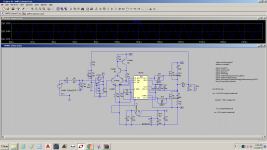
im getting this output now what is wrong in here
I did also test with the models, and get strange outcomes, I do stay in discrete comparators because it is more easy with supply.
and I get almost -100 dB distortion with a fase shift version amp with bessel low pass and no analog feedback... The bessel
low pass needs 24 dB octave.
Attachments

- Home
- Amplifiers
- Class D
- UCD 25 watts to 1200 watts using 2 mosfets