You're welcome!
I use 2 paralleled 2512 in diff mode and 4 1206 in common mode. Probably they will survive the IMD measurement.
I use 2 paralleled 2512 in diff mode and 4 1206 in common mode. Probably they will survive the IMD measurement.
Pafi,
I've been looking at this res. Continuos pulse rating looks good.
http://www.mouser.com/ProductDetail/Vishay-Draloric/RCL122522R0JNEG/
I've been looking at this res. Continuos pulse rating looks good.
http://www.mouser.com/ProductDetail/Vishay-Draloric/RCL122522R0JNEG/
Pafi,
I've been looking at this res. Continuos pulse rating looks good.
http://www.mouser.com/ProductDetail/Vishay-Draloric/RCL122522R0JNEG/
Good, but I think this is the other side of the horse. And more smaller one can distribute heat more evenly.
0805 double sided 0.5W
http://www.mouser.com/ProductDetail/Panasonic/ERJ-P6WJ220V/
0805 single sided 0.5w pulse proof
http://www.mouser.com/ProductDetail/Vishay-Draloric/CRCW080522R0JNEAHP/
1632rev 0.75w
http://www.mouser.com/ProductDetail/ROHM-Semiconductor/LTR18EZPJ220/
http://www.mouser.com/ProductDetail/Panasonic/ERJ-P6WJ220V/
0805 single sided 0.5w pulse proof
http://www.mouser.com/ProductDetail/Vishay-Draloric/CRCW080522R0JNEAHP/
1632rev 0.75w
http://www.mouser.com/ProductDetail/ROHM-Semiconductor/LTR18EZPJ220/
Last edited:
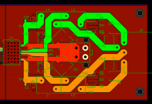
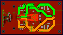
Slowly working through the board. Updated filter network.
Attachments
Last edited:
80% of heat dissipation in this resistors are going into the traces. Wider traces, cooler resistors.
1632rev is the best among these. It can transfer heat well trough the long edges to GND copper, and cheaper than the others.
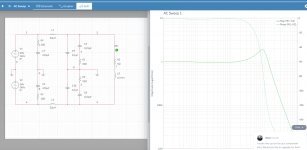
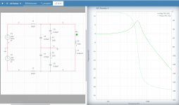
I've developed a circuit on MultiSIM Live. Tentatively modelled on a full range speaker 5ohm/0.7mH. See attached.
This seems better than the original, however high freq is not attenuated very well, just acceptable. Freq scale is not visible. Left side RC snubbers don't do anything in this simulation, but will generate some heat (about 0.1 W on R) in the actual circuit. Single ended circuit is enough for simulation, this way you won't hit into simulation limitation so soon.

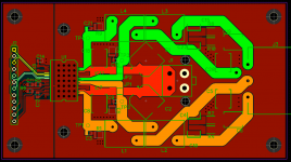
Now trying to decide best way to separate the power stage grounds from the signal ground.
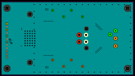
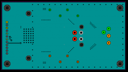
Take care of bottom side also! (I mean show it!)
GND pins of connector should be connected directly to GND polygon on both sides!
The stitching vias are better to extend up and down as much as possible, but a single row is enough. Generally the best is to form a complete guard ring from gnd vias around power stages, but not neccessary here.
PWM inputs should be better kept separated from each other, unless you are sure you don't want to use BD modulation.
Something interesting I tried today. I picked ups a Daweoo KOC9Q1T combo oven for £70.
If you have a look at page 12 of the manual - CONVECTION COOKING(with pre-heat).
The controller allows you to use the convection oven to preheat the oven to 180 for say max 3 mins. It will beep at you when fully preheated.
I then set to 220c for 60-80 seconds. It works really well as a reflow oven. 🙂
http://www.daewooelectronics.co.uk/media/manual/KOC9Q1T_manual.pdf
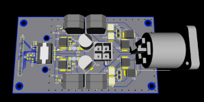
Thanks Pafi, making some changes now - see attached.
Attachments


Last edited:
Thanks for your insight Pafi. It is much apprecieated! Here's a chart with frequency.
You're welcome!
As I thought, the attenuation at switching freq is quite low. This is actually not an audible problem, but it will look nasty on oscilloscope (too high carrier residue).
Thanks Pafi, making some changes now - see attached.
Guard ring should be around the power section only! (Right side of IC.)
Heatsink mounting holes should be much closer to IC if you will use the PCB to transfer the force.
Changed over the the 1632 reverse 0.75W resistors for the out filter. Heatsink holes to 25mm pitch. Still toying with filter topologies.
Attachments

Last edited:
- Status
- Not open for further replies.
- Home
- Amplifiers
- Class D
- Project Moshulu : a journey into class D