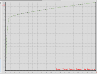
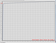
Bob, I took to heart the advice in post #7526 and started simulating the 2T shunt feedback current source in the frequency domain, studying gain and phase. The simulation results seem to be telling meI made a plot of simulated phase margin vs. stray capacitance, image #3 below. As you can see, phase margin crosses zero when Cstray is above 8 picofarads. That's scary!
- Self inductance of the transistor pins (up to 15 nH) doesn't make much difference. I didn't study mutual inductance however.
- The impedance of the load driven by the current source is critical. Lower impedance loads (such as the emitters of an LTP) result in MUCH worse phase margin.
- The ratio of currents between the two transistors doesn't make much difference. I froze it at ten to one so you wouldn't gripe.
- Stray capacitance across the current sense resistor ("R1" in the schematic below) can destroy phase margin.
- Different transistor part#s (i.e. different SPICE model parameters) gave different amounts of phase margin. The Fairchild KSA992 (model supplied by Linear Technology) was worst among the PNPs I tried. The BC560C (model supplied by Cordell Audio) was second worst; it needed 30pF of stray cap to begin oscillating.
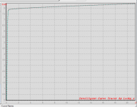
To get the transient simulation results in image #2, I used the LTSPICE directive ".IC" (Initial Conditions) to nudge the simulated circuit away from its metastable state. The LTSPICE deck (.asc file) is attached if anybody wants to horse around with it.
I myself have decided to stop using this particular topology to implement a current source; I've gone to (VREF-VBE)/R circuits, with and without cascode. Mostly, with cascode.
Hi Mark, When I try your .asc file it does not find an LT model for the KSA992, and I have
a fresh install of LTSPICE (V4.23l). Is there an additional model file from LT, or did you mean to say from Fairchild?
"The Fairchild KSA992 (model supplied by Linear Technology) was worst among the PNPs I tried. "
Last edited:
Yikes! I segregated the new and extra models I added to "standard.bjt" down at the bottom of the file, but apparently a subsequent sync of LTSPICE somehow merged and sorted back into the middle of the file. So, when I didn't see that model at the bottom of the file, I just assumed it came from LT. Sorry!
Worse yet, Fairchild seems to have refreshed their models in April of this year, and the parameters on their website today are not the same as the parameters I've got in my standard.bjt file from who-knows-when. Here's the model on their website right now:
BTW it's worthwhile to get a login ID on Fairchild's website, lots of goodies can be yours if you register.
Worse yet, Fairchild seems to have refreshed their models in April of this year, and the parameters on their website today are not the same as the parameters I've got in my standard.bjt file from who-knows-when. Here's the model on their website right now:
Code:
* PSpice Model Editor - Version 9.2
*$
******* Discrete Bipolar Electrical Circuit Model *******
** Product: KSA992
** Package: TO-92
** PNP Epitaxial Silicon Transistor
** Complement to KSC1845
**-------------------------------------------------------
.MODEL KSA992 pnp (
+ IS=4.0544E-13      BF=365.1           NF=1
+ BR=0.20            NR=1.0             ISE=4.0544E-14
+ NE=1.5             ISC=1.0378E-13     NC=1.5
+ VAF=13             VAR=100            IKF=36.498
+ IKR=0.0225         RB=186              RBM=1.04
+ IRB=1.0125E-6      RE=0.0044          RC=0.048
+ CJE=2.3093E-11     VJE=0.855          MJE=0.4404
+ FC=0.5             CJC=6.8251E-12     VJC=0.64
+ MJC=0.2897         XTB=1.2849         EG=1.1603
+ XTI=3              TF=5.86e-10        XTF=4.0
+ ITF=0.024          VTF=4.0            TR=1.0e-8)
**-------------------------------------------------------
** Creation: Apr.-22-2016   Rev:1.0
** Fairchild Semiconductor
*$
BTW it's worthwhile to get a login ID on Fairchild's website, lots of goodies can be yours if you register.
BTW it's worthwhile to get a login ID on Fairchild's website, lots of goodies can be yours if you register.
OnSemi grabbed them earlier this year, so expect dropping from the Fairchild lineup anything that doesn't make 300% profit.
Yikes! I segregated the new and extra models I added to "standard.bjt" down at the bottom of the file, but apparently a subsequent sync of LTSPICE somehow merged and sorted back into the middle of the file. So, when I didn't see that model at the bottom of the file, I just assumed it came from LT. Sorry!
Worse yet, Fairchild seems to have refreshed their models in April of this year, and the parameters on their website today are not the same as the parameters I've got in my standard.bjt file from who-knows-when. Here's the model on their website right now:
Code:* PSpice Model Editor - Version 9.2 *$ ******* Discrete Bipolar Electrical Circuit Model ******* ** Product: KSA992 ** Package: TO-92 ** PNP Epitaxial Silicon Transistor ** Complement to KSC1845 **------------------------------------------------------- .MODEL KSA992 pnp ( + IS=4.0544E-13 BF=365.1 NF=1 + BR=0.20 NR=1.0 ISE=4.0544E-14 + NE=1.5 ISC=1.0378E-13 NC=1.5 + VAF=13 VAR=100 IKF=36.498 + IKR=0.0225 RB=186 RBM=1.04 + IRB=1.0125E-6 RE=0.0044 RC=0.048 + CJE=2.3093E-11 VJE=0.855 MJE=0.4404 + FC=0.5 CJC=6.8251E-12 VJC=0.64 + MJC=0.2897 XTB=1.2849 EG=1.1603 + XTI=3 TF=5.86e-10 XTF=4.0 + ITF=0.024 VTF=4.0 TR=1.0e-8) **------------------------------------------------------- ** Creation: Apr.-22-2016 Rev:1.0 ** Fairchild Semiconductor *$
BTW it's worthwhile to get a login ID on Fairchild's website, lots of goodies can be yours if you register.
If you use an .include statement then you can keep models from other sources
in the included file. However, then I don't think they show up in the menu.
I do this with Bob's models.
I'd like to duplicate your results are the sims nearly the same with the updated file
from Fairchild? Yes, I've had an account with them for many years.
You can also put the .model statement right into the schematic for the design when
you want to be sure that a particular model is used by others, not very convenient
for you though.
Also, in my experience OnSemi SPICE models are pathetic, many that I've tried to
use I'd consider defective. This was a few years ago.
Last edited:
What about current-mirror error? Typical 2 transistor model vs 4 transistor etc etc.
??
THx- RNMarsh
??
THx- RNMarsh
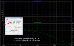
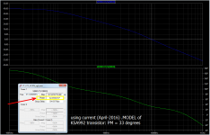
As Murphy's Law would have predicted, the April-2016 spice .MODEL of the KSA992 gives a different answer than the predecessor model.
In a 2T feedback CCS with 154R in the current source emitter leg, 12K in the control transistor collector leg, 1.0R load on the current source collector, 15V supply:
Plots attached below.
And if you try other .models of other transistor types (suggested: Cordell Audio BC560C; Walt Jung favorite PN2907A; 2N4403; etc) you'll get different amounts of phase margin. The circuit is twitchy.
Here is the old model if anyone cares. Notice the GIGANTIC change in VAF among many other changes:
In a 2T feedback CCS with 154R in the current source emitter leg, 12K in the control transistor collector leg, 1.0R load on the current source collector, 15V supply:
old KSA992 model said 6 degrees of phase margin
new KSA992 model says 33 degrees of phase margin
(Nobody should be thrilled with 33 degrees of PM).new KSA992 model says 33 degrees of phase margin
Plots attached below.
And if you try other .models of other transistor types (suggested: Cordell Audio BC560C; Walt Jung favorite PN2907A; 2N4403; etc) you'll get different amounts of phase margin. The circuit is twitchy.
Here is the old model if anyone cares. Notice the GIGANTIC change in VAF among many other changes:
Code:
.model old_KSA992 pnp(
+ IS=5.7544E-14
+ BF=348.1
+ NF=1
+ BR=3.62
+ NR=0.95
+ ISE=5.7544E-15
+ NE=1.5
+ ISC=1.8378E-14
+ NC=1
+ VAF=144
+ VAR=16.68
+ IKF=0.298
+ IKR=0.0525
+ RB=140
+ RBM=16.084
+ IRB=1.4125E-3
+ RE=0.38
+ RC=0.47
+ CJE=2.3093E-11
+ VJE=0.855
+ MJE=0.4104
+ FC=0.5
+ CJC=8.9251E-12
+ VJC=0.5
+ MJC=0.3497
+ CJS=0
+ VJS=0.8
+ MJS=0.33
+ XTB=1.2849
+ EG=1.1603
+ XTI=3
+ XCJC=0.3062
+ mfg=Fairchild )
Attachments
Last edited:
Yikes! I segregated the new and extra models I added to "standard.bjt" down at the bottom of the file, but apparently a subsequent sync of LTSPICE somehow merged and sorted back into the middle of the file. So, when I didn't see that model at the bottom of the file, I just assumed it came from LT. Sorry!
Worse yet, Fairchild seems to have refreshed their models in April of this year, and the parameters on their website today are not the same as the parameters I've got in my standard.bjt file from who-knows-when. Here's the model on their website right now:
Code:* PSpice Model Editor - Version 9.2 *$ ******* Discrete Bipolar Electrical Circuit Model ******* ** Product: KSA992 ** Package: TO-92 ** PNP Epitaxial Silicon Transistor ** Complement to KSC1845 **------------------------------------------------------- .MODEL KSA992 pnp ( + IS=4.0544E-13 BF=365.1 NF=1 + BR=0.20 NR=1.0 ISE=4.0544E-14 + NE=1.5 ISC=1.0378E-13 NC=1.5 + VAF=13 VAR=100 IKF=36.498 + IKR=0.0225 RB=186 RBM=1.04 + IRB=1.0125E-6 RE=0.0044 RC=0.048 + CJE=2.3093E-11 VJE=0.855 MJE=0.4404 + FC=0.5 CJC=6.8251E-12 VJC=0.64 + MJC=0.2897 XTB=1.2849 EG=1.1603 + XTI=3 TF=5.86e-10 XTF=4.0 + ITF=0.024 VTF=4.0 TR=1.0e-8) **------------------------------------------------------- ** Creation: Apr.-22-2016 Rev:1.0 ** Fairchild Semiconductor *$
BTW it's worthwhile to get a login ID on Fairchild's website, lots of goodies can be yours if you register.
This looks like a typical crappy manufacturer's model. VAF of 13 is BS. RE of 0.0044 is BS. RC of 0.048 is BS. Some numbers look semi-reasonable. This is what comes out when they just throw a transistor into an automated modeler.
Its not always clear how they measure to get VAF (Early effect), but if they do it with a DC measurement that allows warmup of the junction at higher test voltages, VAF will come out low.
Cheers,
Bob
Mark, we have been reporting SPICE model problems on here going back probably 8 to 10 years,
most from the manufacture's are crap. I reported problems here back in 2007:
http://www.diyaudio.com/forums/soli...je-990-op-amp-deane-jensen-2.html#post1290867
andy_c and Bob have done some nice work but I don't trust most others.
I think it would be interesting to build the 2T current source in real hardware and test a few
different devices.
I'll try your sim again with the old model just for kicks when I get a chance.
Last edited:
For newer members: Mike K. used to be on this forum, here is a thread with a link to Michael Kiwanuka's SOA paper:
http://www.diyaudio.com/forums/solid-state/235841-michael-kiwanukas-soa-paper.html
I seem to remember discussing SOA with him and generally agreeing but not 100%.
A very old SOA discussion:
http://www.diyaudio.com/forums/solid-state/49255-safe-operating-area.html
http://www.diyaudio.com/forums/solid-state/235841-michael-kiwanukas-soa-paper.html
I seem to remember discussing SOA with him and generally agreeing but not 100%.
A very old SOA discussion:
http://www.diyaudio.com/forums/solid-state/49255-safe-operating-area.html
Last edited:
speaking of models ....
Audio Precision's latest email (at least it hit "my" email box today) has a nice bit on "erroneous" Rb values provided in BJT models and impacts. some interesting comments on stability since we've been looking at potentially unstable current sinks/sources.
don't know if it's posted on their web site yet.
mlloyd1
Sometimes I have put a light Zobel network shunting the VAS output node to ground to keep the impedance on that node a little more real for better phase margin, and that may also add some stability to the 2T CCS, helping to keep that node from looking inductive. I usually use 47pF and 100 ohms in series.
Bob, you are very generous in taking the time to craft these replies which always contain valuable nuggets of info. I'm hopeless with the simulator (because I don't understand all the theory well enough) so real-life trial and error is the only way for me.
My take away from Mark's comments is that I've been very lucky to date, because the stability margins for the 2T CCS with the components I'm using are ridiculously slender, so I've decided to adopt the shunt compensation network described in Michael K's paper as well as the resistor you suggested in the next rev. of my amp. We are talking about five cents worth of added components per CCS - I can live with that for the peace of mind!
Attachments
Last edited:
Bob, you are very generous in taking the time to craft these replies which always contain valuable nuggets of info. I'm hopeless with the simulator (because I don't understand all the theory well enough) so real-life trial and error is the only way for me.
My take away from Mark's comments is that I've been very lucky to date, because the stability margins for the 2T CCS with the components I'm using are ridiculously slender, so I've decided to adopt the shunt compensation network described in Michael K's paper as well as the resistor you suggested in the next rev. of my amp. We are talking about five cents worth of added components per CCS - I can live with that for the peace of mind!
I agree completely that a few extra components are no big deal, as long as they don't significantly degrade performance or have other unintended consequences. This goes double in the SMT world where space is less of an issue. I'm not sure that Mike's shunt compensation values are optimal for all current source component values, etc. You have to go with what you are comfortable with. There have been numerous times when I've stuck a 100 ohm resistor at one of the inputs of a high-speed op amp just to be on the safe side.
I don't know how much experience you've had with LTspice, but I urge you not to give up on it. It provides tremendous insight, and can help a lot in regard to mistakes and/or issues that are non-intuitive in the operation of the design. If you haven't, you might want to go to my web site and download and play with a couple of ready-to-run quasi-tutorial examples.
In your circuit, you should split the resistors that bias the CCS control transistors and place a bypass capacitor from there to the rail. This will give you a bit more PSRR at audio frequencies.
Cheers,
Bob
Here's an IV curve of a KSA992 that I measured myself, last month. Beta is 500 and Early Voltage is 82 volts. Note the slight whiff, the faint odor, of quasi-saturation.
A couple of things to bear in mind regarding Early voltage and VAF.
The thing that really matters most at the end of the day in most circuits like those in audio amplifiers is figure of merit that is the product of Beta and Early voltage. This is what really determines the output impedance in most CE applications. In the case you cited, the FM is 41,000, which is not bad, but not super, either. In some respects, a really high Beta transistor "has a right" to have a smaller Early voltage.
Secondly, the Early effect in reality can be nonlinear and a function of the operating current of the transistor. If we have to pick a single value for VAF in the idealized SPICE model, it should be established at a reasonably low operating current for that device. This also reduces temperature effects that may come into play. In your example, that small-signal TO-92 device is dissipating almost 200mW at the high end of the curve. For SPICE modeling purposes, VAF for that transistor should probably be determined at a current more like 1mA or even less.
Cheers,
Bob
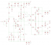
Q112 limits too early.Bob, you are very generous in taking the time to craft these replies which always contain valuable nuggets of info. I'm hopeless with the simulator (because I don't understand all the theory well enough) so real-life trial and error is the only way for me.
My take away from Mark's comments is that I've been very lucky to date, because the stability margins for the 2T CCS with the components I'm using are ridiculously slender, so I've decided to adopt the shunt compensation network described in Michael K's paper as well as the resistor you suggested in the next rev. of my amp. We are talking about five cents worth of added components per CCS - I can live with that for the peace of mind!
the 75r develops ~400mVbe when Ic = 5.3mApk that's the protection transistor just starting to turn on and reaching full limiting @ ~7mApk
Q109 is passing ~6mA, i.e. the protection transistor has already entered protection when there is zero signal and only quiescent current.
R121:R115 should be around 1:3 for value.
If you need 100r and 75r of degeneration then you can split the 75r into 43r and 33r. The 33r attached to the negative rail starts to turn on Q112 @ ~12mApk This allows the stage to pass signals almost reaching ±5.5mApk without the protection introducing distortion as it turns on.
Q113 probably needs a protection resistor in it's collector lead.
Last edited:
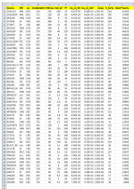
I measured a bunch of PNP transistors and calculated that figure of merit; it's in column "L" of the table below. Beta was measured at (10V & 1mA) and Early voltage was measured at (10V & 8mA). Those were the measurement conditions that most closely met my design needs at the time; readers who don't approve of these choices are, of course, free to repeat the measurements themselves at whatever conditions they prefer.The thing that really matters most at the end of the day in most circuits like those in audio amplifiers is figure of merit that is the product of Beta and Early voltage.
The KSA992 comes out 11th best (see row 12) in this table. The 2N5401, used throughout Bob's book, winds up in 23rd position, with a Figure Of Merit that's 83% as good as the KSA992. Notice that the top two finishers are large, macho power transistors, and number 3 is the lowly MJE350 medium power device in TO-126 packaging.
It's a big image and the DIYA forum software doesn't display it full-size unless you click on the white cross at bottom left of the image. So, click that please.
_
Attachments
Q112 limits too early.
the 75r develops ~400mVbe when Ic = 5.3mApk that's the protection transistor just starting to turn on and reaching full limiting @ ~7mApk
Q109 is passing ~6mA, i.e. the protection transistor has already entered protection when there is zero signal and only quiescent current.
R121:R115 should be around 1:3 for value.
If you need 100r and 75r of degeneration then you can split the 75r into 43r and 33r. The 33r attached to the negative rail starts to turn on Q112 @ ~12mApk This allows the stage to pass signals almost reaching ±5.5mApk without the protection introducing distortion as it turns on.
Q113 probably needs a protection resistor in it's collector lead.
Note that when the VAS is in current limiting it pretty much looks like the 2T feedback current source, so some stability considerations might apply (although at this point the amplifier has much bigger problems).
Cheers,
Bob
I measured a bunch of PNP transistors and calculated that figure of merit; it's in column "L" of the table below. Beta was measured at (10V & 1mA) and Early voltage was measured at (10V & 8mA). Those were the measurement conditions that most closely met my design needs at the time; readers who don't approve of these choices are, of course, free to repeat the measurements themselves at whatever conditions they prefer.
The KSA992 comes out 11th best (see row 12) in this table. The 2N5401, used throughout Bob's book, winds up in 23rd position, with a Figure Of Merit that's 83% as good as the KSA992. Notice that the top two finishers are large, macho power transistors, and number 3 is the lowly MJE350 medium power device in TO-126 packaging.
It's a big image and the DIYA forum software doesn't display it full-size unless you click on the white cross at bottom left of the image. So, click that please.
_
Nice work, Mark.
For the FM, I would recommend that Beta and Early voltage should be measured at the same current. Ditto for modeling purposes to establish VAF.
I seem to remember that the MJE350 had a bad reputation for use as a VAS transistor, at least in simulation, due to Early effect. I think I noted to myself that when I characterized the MJE250 that Early voltage was much higher than the commercial models indicated. Assuming that the 240 and 340 share some similarities in FM, it is refreshing to see that your measured numbers are quite good for the MJE350.
I would like some comments from anyone on the approach of determining VAF by the use of small-signal 1kHz ac Zout measurements at a nominal typical operating point. This may be more pertinent to actual circuit behavior and largely eliminates any error introduced by junction temperature effects in measurement (resulting from Beta's dependence on junction temperature).
Cheers,
Bob
Mark thanks for a very useful table!
Bob, your 2nd edition will become a must-have for all of us here!
Jan
Bob, your 2nd edition will become a must-have for all of us here!
Jan
Here is the "350" from 3 different manufacturers and in both SMD (MJD) and thru-hole (MJE) packages. Hover over the image to read the device type, embedded in the filename. Not a lot of variability among them.
Attachments


- Home
- Amplifiers
- Solid State
- Bob Cordell's Power amplifier book