Here in Germany resistors with 0.1% tolerance are easily achievable, but not too cheap, though. Otherwise - what about a trimpot?
Sure, could be done with a trimpot, but can also quite easily be done by actually measuring and matching those resistors. Perhaps with a wheatstone bridge or some rig like that. Nothing too difficult and pretty cheap, and the result I think is worth the effort. I surely would do that myself.
Doesn't look too bad, does it? It might have an impact on the clippling behaviour only, I suspect.
I suspect actually a little more effect than on clipping. It may add a little bit more thd. I've seen many times while tweaking amps that when they're not well balance, the thd is usually a little higher. So a simple extra effort to match parts can make a nice difference.
One other thing I would do with the ltp pairs, and actually while at it, why not all of those pairs? Is to face their flat part of their case to each other, put a tiny bit of thermal paste and then tie them together tightly, for better thermal matching.
This can be done for the ltp, mirrors, current sources and even sziklai pairs. It's only a simple matter of pcb layout to have them face each other properly and close enough to be in contact.
On the pcb, it would also be best to keep those small signal stages as far away as possible from the heatsinked ones.
So many little details like this, but it makes for a better result.
I think the critical devices to match and thermally track are the input transistors, both pairs. I do wish we had quad complementary matched parts, but they come and go from production. Probably we should hand match in pairs from the best low noise parts in long production.
I keep trying to imagine where the upswing of LF noise comes from. The double RC filter was not helpful. Looking at the current sources, perhaps the inputs to them are not filtered with respect the the proper reference. Purely as a trial, I put in a filter referenced to the same side rails in the schematic attached. I doubt this is the solution, but it is worth testing.
I keep trying to imagine where the upswing of LF noise comes from. The double RC filter was not helpful. Looking at the current sources, perhaps the inputs to them are not filtered with respect the the proper reference. Purely as a trial, I put in a filter referenced to the same side rails in the schematic attached. I doubt this is the solution, but it is worth testing.
Attachments
I think the critical devices to match and thermally track are the input transistors, both pairs.
That's the bare minimum, but nothing prevents by good layout to implement this further into each pair, mirrors, sources and even sziklai. It's only pcb layout, then when they're facing each other, it's no big deal to slap on a tiny bit of thermal grease and tie them together.
Plus pairing up each pair of resistors can definitely help as well not just the centering ones, all of them in the ltp area. It's so easy to do, why not go the extra mile if you're building an amp you want to be proud of.
I do wish we had quad complementary matched parts, but they come and go from production.
There was, for a while, matched pairs in dip cases, some with npn/pnp pairs. No better thermal matching, and logically the other aspects of matching should be pretty well done. I think they adjust them before casing by laser, so they bring them as close as they can
However as you point out, for some reason those don't stay on the market very long.
Probably we should hand match in pairs from the best low noise parts in long production.
Definitely the way to go, and the BC550/60C are still available and using the C insures the highest gain. Those are very nice low noise and perfect for our usage.
I keep trying to imagine where the upswing of LF noise comes from. The double RC filter was not helpful.
I'm puzzled too, but I didn't think any noise came from the sources, and since we had no series resistance in the voltage sources for the low rails, nothing could really come from there. Being ideal that way is why the extra RC filters didn't change anything.
But with added series resistance, I don't think noise would be the issue, at least not in the simulations. It would be more ripples that would be created, by the vas.
Perhaps in a real power supply, with regulators and all that, some noise could come in that way, and maybe having the extra RC filters there could help.
Looking at the current sources, perhaps the inputs to them are not filtered with respect the the proper reference. Purely as a trial, I put in a filter referenced to the same side rails in the schematic attached. I doubt this is the solution, but it is worth testing.
Apparently it doesn't change anything.
My reasoning on this is that having seen how quiet everything is in the sources, I don't think they bring in any noise to speak of, and since the major contributors in the ltp pairs are the ones on the in+ side only, I figure if noise was coming from the sources, both sides would be fairly equally affected.
I don't think there is a lot to worry about there anyway, because this is mostly below 10hz, so it wouldn't be a noisy hiss but rather a very low hum, which is below the human hearing threshold anyway. And this is still not a huge amount to begin with.
Attachments


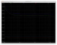
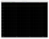
Here is a run down again of the noise contributions, with the topo as we have it now.
Starting with the active first. Then I'll post the resistors next.
Starting with the active first. Then I'll post the resistors next.
Attachments
-
 Screen Shot 2016-12-14 at 10.19.15 PM.png227.2 KB · Views: 56
 -
 Screen Shot 2016-12-14 at 10.18.18 PM.png246.4 KB · Views: 56
 -
 Screen Shot 2016-12-14 at 10.17.49 PM.png243.9 KB · Views: 63
 -
 Screen Shot 2016-12-14 at 10.17.03 PM.png251.9 KB · Views: 135
 -
 Screen Shot 2016-12-14 at 10.17.16 PM.png696.1 KB · Views: 137
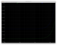
I couldn't post all of the resistors, so more coming next.
Attachments
-
 Screen Shot 2016-12-14 at 10.24.32 PM.png221.1 KB · Views: 44
 -
 Screen Shot 2016-12-14 at 10.24.14 PM.png249.4 KB · Views: 62
 -
 Screen Shot 2016-12-14 at 10.23.54 PM.png245.8 KB · Views: 47
 -
 Screen Shot 2016-12-14 at 10.23.20 PM.png277.5 KB · Views: 52
 -
 Screen Shot 2016-12-14 at 10.22.21 PM.png247.4 KB · Views: 51
 -
 Screen Shot 2016-12-14 at 10.21.58 PM.png252 KB · Views: 52
 -
 Screen Shot 2016-12-14 at 10.21.23 PM.png258.2 KB · Views: 48
 -
 Screen Shot 2016-12-14 at 10.21.02 PM.png254 KB · Views: 43
 -
 Screen Shot 2016-12-14 at 10.20.39 PM.png259.1 KB · Views: 47
 -
 Screen Shot 2016-12-14 at 10.20.08 PM.png225.8 KB · Views: 48
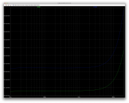
Here's the last batch.
All this should give a bit of an overview.
I'm surprised how noisy the base stoppers are in the CM.
There is still a somewhat sizable difference between one side and the other, in most places.
I have the impression that the input pair has a little less impact than previously. Compared to their counterparts on the feedback side of it.
Attachments

I'm wondering about something.
What are the implications of using much bigger filter caps (the 4700u)?
Besides bandwidth at the low end of course.
How are those calculated?
Is their sizing somewhat arbitrary? A choice for compromise?
What are the implications of using much bigger filter caps (the 4700u)?
Besides bandwidth at the low end of course.
How are those calculated?
Is their sizing somewhat arbitrary? A choice for compromise?
I'm thinking about a good heatsink for this amp.
What about that MF30-1F-75 from conradheatsinks?
Conrad Heatsinks - Products
Looks great and 0.37C/W is probably quite enough.
With a 300mm length, it would be a little tight to put everything on it, but I suspect it could be done.
Of course that would make for a pcb layout rather long and narrow, with all the power devices on one edge.
With such a tight layout, it might be a little tricky to bring out the output neatly and eventually have the output plug right on the pcb...
But wouldn't it be neat to have everything on a single pcb, with the input and output plugs, the filter caps, and even the rectifier bridge? hardly any wiring needed, just the transformer's wires to the pcb.
Still trying to figure out why the tian probe results are inconsistent and why it's not working as expected.
No one has come forth to correct my use of the tian probe and point us in the right direction.
I tried the tian probe in a simpler manner and it's still giving the same type of results.
For one thing, although we have an amp that should have a somewhat low open loop gain, I think it should be at least some 70-80db, hopefully a little more, but nothing like the tian probe seems to say, which is much less open loop gain than we have closed loop. Makes no sense.
I have tried inserting the probe in various ways. It should be somewhere in the global loop, so there aren't too many choices.
Something doesn't add up. But what?
Attachments
Trying to understand that odd tian probe result. I investigated the open loop gain situation.
Well, apparently the tian probe may not be lying after all. We do have a very very low open loop gain, and that's probably why our thd readings have a hard time getting low.
I cut off the global feedback to see what happens, and surprise! The amp is biasing, stable and works just fine in open loop, and the gain really isn't much.
I brought it to early clipping with 400mV (open loop!!!), and although we see the onset of clipping and we can visually detect some distortion, the thd reading really isn't even bad for an amp with no global feedback.
I guess we're spending a little too much of the open loop gain in some inner stages in local feedback.
We should release some of that spent gain into the open loop, and work with more open loop gain.
This would not only bring thd down, but it should also make the amp somewhat more stable, and then the tian probe might give more consistent readings too.
Amazingly, with no global feedback, the amp centers perfectly, only with those 2 resistors, and each stage's feedback and centering stuff keeps it rather well balanced.
The output stages need to have a little bit of gain, but we're not taking all the advantages of the input stages' available gain. Too strong of local feedback consumes too much of those stages' gain.
Attachments
I guess we're spending a little too much of the open loop gain in some inner stages in local feedback.
We should release some of that spent gain into the open loop, and work with more open loop gain.
This would not only bring thd down, but it should also make the amp somewhat more stable, and then the tian probe might give more consistent readings too.
Hi spookydd,
the difference between the design that you've elaborated here and the QSC/Crown originals is the opamp in the input with ample of open loop gain. Maybe a discrete, but opampish input section could be the solution? Otherwise all efforts seem to come close to, pardon me to say that, riding a dead horse, maybe.
Best regards!
the difference between the design that you've elaborated here and the QSC/Crown originals is the opamp in the input with ample of open loop gain.
That was the point, not to use opamps.
Maybe a discrete, but opampish input section could be the solution? Otherwise all efforts seem to come close to, pardon me to say that, riding a dead horse, maybe.
Not so fast!
It's nothing to worry about. We're talking about releasing from local closed loops a little of the gain that is already present.
We're not lacking gain. It's just tied up a little too much in inner loops.
We don't have to touch the power half, just get some back from the front end, and there should be plenty of it for that.
The ltp with sziklai and mirrors has quite enough gain, and we just need to let some more available to the open loop instead of feeding it back on itself a little too much.
As it stands now, despite this open loop gain missing, and thus the effect of the global feedback being very weak or non-existent, we already are able to have a fairly stable amp and although it does have a little more thd than we would hope, it does this with just about no global feedback. This means once we set loose a bit more open loop gain, the global feedback will be able to get things more under control and we should see the thd drop quite a bit.
I think we're actually pretty close to the goal now.
What is our gain in the ltp stage?
I'm not versed in calculations with that "transconductance" and such things.
I was thinking, most common amps have a voltage gain mostly in the 100-120db range, and most of them don't have gain in their output stages.
Whatever gain may be in the vas stage, wouldn't be much.
So I guess in most designs, the bulk of the gain is from the input stage, and the ltp stage is pretty good at providing that.
In our case, if we have a gain in the output stage in the 4-5 range, and let's assume we had an open loop gain (on the high side, for ease of calculation) of some 100db, counting on basically no gain from the vas, our ltp stage would need to provide a gain in the 20000 range, taking 5 for the output stage, and nothing for the vas.
Now I think we do have some vas gain, but how much?
What else besides that dc feedback 33k res determines the output stage gain?
We no longer use the local feedback from the vas, so unless we have a few points of gain in the vas, we need to get some from the ltp.
Now we don't even have to aim for 100db or more of open loop gain. We could deal with much less, perhaps a more modest 70-80db? Or 90db if need be.
That changes things quite a bit, and an ltp stage is capable of quite a bit of gain.
We can favor linearity for low htd and some speed for good slew rate. The degen res on the ltp and the mirrors affect this.
A good compromise would be good.
One other thing, as I was reading some "self" a little more, I read the part where he mentions the mirror's propensity to cause quite a bit of noise and the use of the degen res not only improves that, it also reduces the effect from device's disparities.
I also was looking over at the part where he compares the various mirror topos, and the wilson topo, although adding a serious amount of complexity and part count, has some advantages as well.
We already have the sziklai pair and those seem pretty good to have, and thus I'm wondering if adding a more complex mirror is worth the extra complexity.
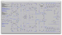
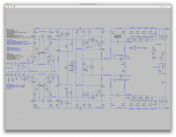
This discussion started with the intent of just modeling a grounded collector amp in Spice. After many simulations and design changes, that was accomplished.
Along the way we experimented with 3 fundamentally different input stages, first with a symmetric current feedback topology, second with an asymmetric discrete op amp topology, and third with this symmetric topology. The symmetric CFA worked OK, but had higher distortion than we felt was acceptable, and low input impedance. The asymmetric topology never worked, probably because we did not use the necessary DC feedback from the floating supply voltages for the output. It probably could be made to work, with that feedback. The last approach simulates well with the DC feedback.
This grounded collector design is unusual because the output stage has a floating DC supply voltage and enormous voltage gain. As we discovered, that makes it difficult to control, unless strong DC feedback from the floating supply voltages is a major component of the global negative feedback. We're using a mix of this DC feedback and more traditional output feedback in about a 1:4 ratio, which we found empirically works best. We also found that the output stage would oscillate unless a very high capacitive feedback was used on the driver stage, approximately 1200pF at present. Despite that large value, the amp has good high frequency performance in the audio range, so that probably stays.
It would be good to reduce distortion a bit, keeping the stability we fought hard for. Now that this is working, changes must be done cautiously in small steps. So I will suggest some small modifications which we need to model a step at a time. The first is a cascode on the current source.
Attachments

This discussion started with the intent of just modeling a grounded collector amp in Spice. After many simulations and design changes, that was accomplished.
Definitely. And now it's working quite well. And we've learned a few things along the way. And using the fully symmetric topo I think is always better than not.
It would be good to reduce distortion a bit, keeping the stability we fought hard for. Now that this is working, changes must be done cautiously in small steps. So I will suggest some small modifications which we need to model a step at a time. The first is a cascode on the current source.
Alright, we err on the side of caution.
Looking good so far.
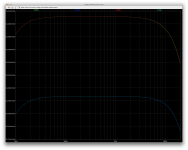
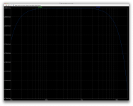
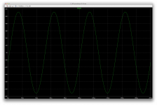
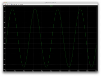
We're at 1.35V input, bringing it to a little before the onset of clipping.
I started at 20khz and went down from there to 1k, 200 and then 20, and even at 20 it looks rather nice.
Took a quick look at noise as well, but no real change since the last incarnation.
Is this level of noise enough to be heard? Maybe not.
Depends a lot I guess on the speaker's efficiency.
At this point I don't think there are many ways to lower that noise, and I don't think multiplying the devices in parallel as self mentions to reduce noise would be a workable option. It's cheap, but layout complex and too many parts.
Attachments
-
 Screen Shot 2016-12-19 at 9.34.16 PM.png240.3 KB · Views: 60
 -
 Screen Shot 2016-12-19 at 9.33.07 PM.png45.9 KB · Views: 61
 -
 Screen Shot 2016-12-19 at 9.32.27 PM.png46.7 KB · Views: 64
 -
 Screen Shot 2016-12-19 at 9.31.30 PM.png47.3 KB · Views: 97
 -
 Screen Shot 2016-12-19 at 9.29.52 PM.png47.1 KB · Views: 94
 -
 Screen Shot 2016-12-19 at 9.30.15 PM.png210.1 KB · Views: 102
 -
 Screen Shot 2016-12-19 at 9.30.27 PM.png701.3 KB · Views: 107
Since the previous measurements were at clipping, hard to compare. Can you run the sim at this power on the previous version for easy comparison?
I expected a slight reduction in noise and possibly slight reduction in THD. We're playing a numbers game probably, improvements perhaps inaudible. The reality is speakers will contribute so much more. But I'd like to understand if a stiffer current source does improve noise or distortion figures, or is a waste of parts.
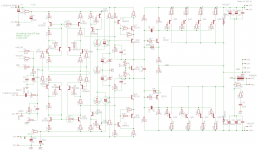
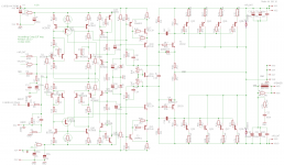
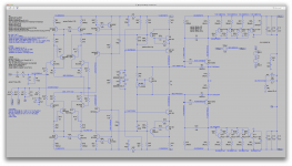
The next step might be enhanced current mirrors, "gilding the lily" perhaps, but since we have this beautiful simulation capability, why not? I've slightly changed the current mirror, using the base current compensation concept from the ancient history. Wilson's mirror would shift levels and require changes downstream, so I chose this alternative configuration. If need be we can try one of the Wilson versions later.
I hope this does not add new problems with stability and gives a slight distortion reduction. We may or may not need base stopper resistors, but I've left them out to make this a quick change (and because you mentioned they added noise). If possible, any measurements should be at the same power levels as the previous version for comparison purposes.
I expected a slight reduction in noise and possibly slight reduction in THD. We're playing a numbers game probably, improvements perhaps inaudible. The reality is speakers will contribute so much more. But I'd like to understand if a stiffer current source does improve noise or distortion figures, or is a waste of parts.
The next step might be enhanced current mirrors, "gilding the lily" perhaps, but since we have this beautiful simulation capability, why not? I've slightly changed the current mirror, using the base current compensation concept from the ancient history. Wilson's mirror would shift levels and require changes downstream, so I chose this alternative configuration. If need be we can try one of the Wilson versions later.
I hope this does not add new problems with stability and gives a slight distortion reduction. We may or may not need base stopper resistors, but I've left them out to make this a quick change (and because you mentioned they added noise). If possible, any measurements should be at the same power levels as the previous version for comparison purposes.
Attachments
Since the previous measurements were at clipping, hard to compare. Can you run the sim at this power on the previous version for easy comparison?
I haven't changed the input level since it had been adjusted when the overall gain changed.
What I meant by before clipping, is that that signal level brings it very close to clipping, but before it actually does.
We've been using the same 1.35V input level since that gain change.
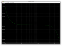
I just ran it at 1.4V at 20 and 20khz, and we can see the early clipping clearly at 20hz, and oddly it's asymmetric at 20khz, because we can only detect it on the positive side and the negative side looks intact.
We have much less clipping at 20khz simply because of the tiny drop of gain at that frequency.
I will try to edge closer to the onset of clipping to see how far 1.35V was. We do know 1.4V already makes it clip distinctly.
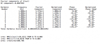
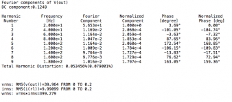
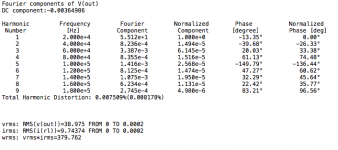
I expected a slight reduction in noise and possibly slight reduction in THD.
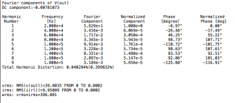
The noise doesn't seem to have changed, but the thd seems better.
The next step might be enhanced current mirrors, "gilding the lily" perhaps, but since we have this beautiful simulation capability, why not?
Sure. I have been wondering what would happen if we stacked 2 mirrors on each other, making an enhanced wilson mirror. Self compares many mirror variants and although the part count does increase every time the basic mirror is enhanced, there are improvements with the better mirrors. However we have to keep in mind the part count and complexity, and the fact that at some point we may have diminishing returns.
Wilson's mirror would shift levels and require changes downstream, so I chose this alternative configuration. If need be we can try one of the Wilson versions later.
Yes, stacking 2 mirrors would definitely requite adjustments for level.
I hope this does not add new problems with stability and gives a slight distortion reduction.
About stability, although it may seem stable in those simulations, I do have concerns, because as I mentioned earlier, I haven't got coherent results from using the tian method to get phase and gain margin.
And it seem I wasn't using the tian probe wrongly, but rather those odd results are what they are and they seem to be revealing a lack of sufficient open loop gain.
That's why I was wondering about trying to let loose a little bit more gain from our locally fed back input stage, to have a little more open loop gain, which would not only help with stability, but also more feedback would reduce thd at the same time. Don't know what that would do to noise...
We may or may not need base stopper resistors,
I have the impression that they are not needed for stability. We didn't have oscillations before that were stopped by their presence.
but I've left them out to make this a quick change (and because you mentioned they added noise).
Yes, they did bring up more noise, and perhaps since they may not really be needed for stability, it might be better not to use them. At least only the ones in the sources, and perhaps the mirrors.
If possible, any measurements should be at the same power levels as the previous version for comparison purposes.
It is, only perhaps the wording I used caused a confusion about the level, but since we changed the global closed loop gain, it's been 1.35V input and hasn't changed.
Still, just by curiosity, I will try to edge closer to clipping, to gauge how far away from actual clipping we are at 1.35V.
I thought the clipping was fairly clean at 1.4V. I wonder what much harder clipping would look like...
Attachments
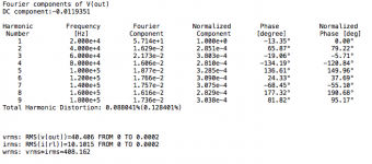

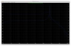
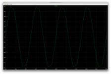
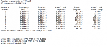
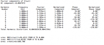
I tried to get closer to clipping with a slightly higher input level, and since it doesn't start clipping at the same level at all frequencies, the best level of reference I suppose is the one at 1khz.
The 1.35V input level that I've been using as being "before the onset of clipping" since the closed loop change made earlier, is in fact really close, and works at all frequencies of interest.
It only takes an extra 20mV to bring it to clipping at each end of the audio spectrum, although 1.37V won't make it clip at 1khz, it does a little at 20khz and also at 20hz.
What's odd, looking at how it clips, is that is starts clipping at the negative side first at 20hz, while it's at the positive side at 20khz.
Slight clipping doesn't seem brutal, but I'll have to take a look at what happens with harder clipping, as we had serious oscillations triggered when hard clipped before.
Attachments
-
 Screen Shot 2016-12-20 at 11.17.25 AM.png46.5 KB · Views: 53
 -
 Screen Shot 2016-12-20 at 11.17.41 AM.png217.5 KB · Views: 55
 -
 Screen Shot 2016-12-20 at 11.16.47 AM.png44.2 KB · Views: 48
 -
 Screen Shot 2016-12-20 at 11.16.35 AM.png214.9 KB · Views: 46
 -
 Screen Shot 2016-12-20 at 11.15.46 AM.png46.3 KB · Views: 46
 -
 Screen Shot 2016-12-20 at 11.15.38 AM.png219.3 KB · Views: 55
 -
 Screen Shot 2016-12-20 at 11.15.29 AM.png516.7 KB · Views: 51
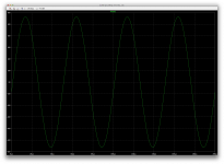
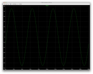
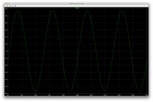
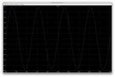
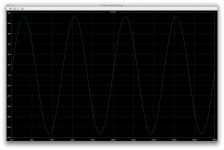
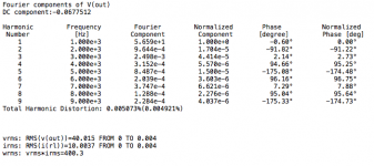
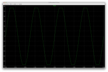
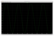
Here it is at higher input level, 1.5V, harder into clipping.
We see a little hint of oscillations when hard clipping at 20khz, and the clipping looks slanted at 20hz, but looks even and straight at 1khz.
We see a little hint of oscillations when hard clipping at 20khz, and the clipping looks slanted at 20hz, but looks even and straight at 1khz.
Attachments
-
 Screen Shot 2016-12-20 at 11.27.46 AM.png46.9 KB · Views: 48
 -
 Screen Shot 2016-12-20 at 11.27.38 AM.png214.5 KB · Views: 46
 -
 Screen Shot 2016-12-20 at 11.28.17 AM.png45.7 KB · Views: 44
 -
 Screen Shot 2016-12-20 at 11.28.09 AM.png215.2 KB · Views: 57
 -
 Screen Shot 2016-12-20 at 11.27.08 AM.png46.7 KB · Views: 52
 -
 Screen Shot 2016-12-20 at 11.27.21 AM.png215 KB · Views: 49
 -
 Screen Shot 2016-12-20 at 11.26.59 AM.png701.7 KB · Views: 49
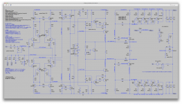
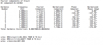
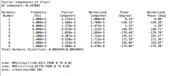
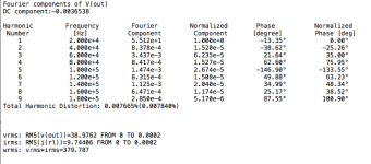
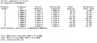
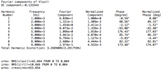
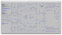
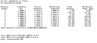
The addition of the 2 extra trannies on the mirrors isn't bringing an appreciable difference, if any.
Actually it does change the biasing and we end up with a few less mA in the vas bias.
At 20k, 1k and 20hz, no real difference in thd, although perhaps a tiny one at 1k, but nothing to warrant this change.
Noise wise, same thing, about the same.
So I guess this mod isn't the way to go.
Actually it does change the biasing and we end up with a few less mA in the vas bias.
At 20k, 1k and 20hz, no real difference in thd, although perhaps a tiny one at 1k, but nothing to warrant this change.
Noise wise, same thing, about the same.
So I guess this mod isn't the way to go.
Attachments
-
 Screen Shot 2016-12-20 at 11.47.30 AM.png693 KB · Views: 61
 -
 Screen Shot 2016-12-20 at 11.47.55 AM.png212.6 KB · Views: 55
 -
 Screen Shot 2016-12-20 at 11.48.05 AM.png46.1 KB · Views: 55
 -
 Screen Shot 2016-12-20 at 11.49.51 AM.png47 KB · Views: 52
 -
 Screen Shot 2016-12-20 at 11.51.11 AM.png46 KB · Views: 49
 -
 Screen Shot 2016-12-20 at 11.51.47 AM.png229.4 KB · Views: 53
- Status
- Not open for further replies.
- Home
- Amplifiers
- Solid State
- grounded collector amp