I just tried a few things with a few more simulated speakers, and they're not performing as I would expect. That first one that I used was fairly good as a normal woofer, but the others are different, so I'm not sure what to think for now.
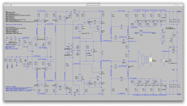
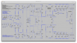
I went back to plain resistive load and kept using the 75V rails.
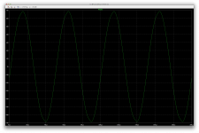
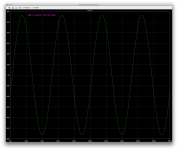
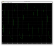
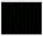
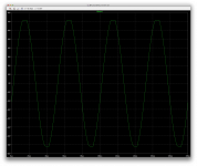
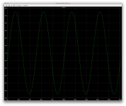
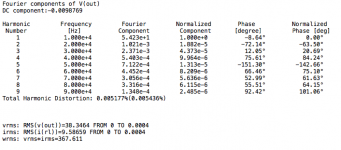
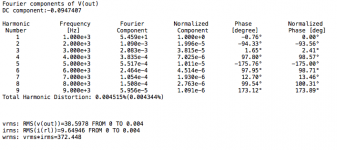
It looks great on 8ohms load, but then I tried it at 4ohms and things get a little worse, which is rather a concern, because loads can and do go down in impedance that way in the real world.
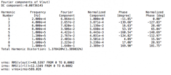
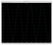
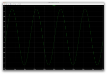
The sine wave looks a little degraded, and that reflects on thd.
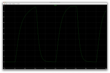
The squares are also a lot more visually degraded, but still no signs of oscillations though.
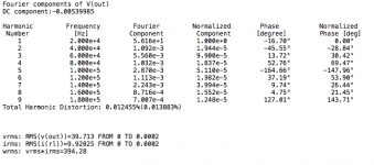
One thing to keep in mind, is that rails are now at 75V and it's a 4ohms load, so we're pumping out nearly 600Wrms.
Still, it does have a behavior that looks like something is sagging.
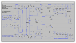
I did all this with a single resistor between the ltp current sources.
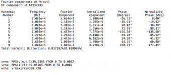
With this configuration, I took a quick look at noise, and while at it, I tried splitting the single res into 2 between the sources, with a cap going to ground, and took an other look at noise. This doesn't improve noise performance though, so I went back to the single res.
One more thing about noise, is that upping the value on that single res actually reduces noise a little. And I guess this makes sense, although a higher value should be noisier, it's actually not because the higher value also reduces the current going through it, so since the noise is proportional to the current, we actually get a small improvement in noise with a higher value. This does work, but not sure what the ramifications will be for other things.
The noise probably could be better, but it's not too bad and I think likely inaudible at that level.
We can probably improve this.
But what should get more improvement is the low impedance load situation.
I went back to plain resistive load and kept using the 75V rails.
It looks great on 8ohms load, but then I tried it at 4ohms and things get a little worse, which is rather a concern, because loads can and do go down in impedance that way in the real world.
The sine wave looks a little degraded, and that reflects on thd.
The squares are also a lot more visually degraded, but still no signs of oscillations though.
One thing to keep in mind, is that rails are now at 75V and it's a 4ohms load, so we're pumping out nearly 600Wrms.
Still, it does have a behavior that looks like something is sagging.
I did all this with a single resistor between the ltp current sources.
With this configuration, I took a quick look at noise, and while at it, I tried splitting the single res into 2 between the sources, with a cap going to ground, and took an other look at noise. This doesn't improve noise performance though, so I went back to the single res.
One more thing about noise, is that upping the value on that single res actually reduces noise a little. And I guess this makes sense, although a higher value should be noisier, it's actually not because the higher value also reduces the current going through it, so since the noise is proportional to the current, we actually get a small improvement in noise with a higher value. This does work, but not sure what the ramifications will be for other things.
The noise probably could be better, but it's not too bad and I think likely inaudible at that level.
We can probably improve this.
But what should get more improvement is the low impedance load situation.
Attachments
-
 Screen Shot 2016-12-10 at 10.38.01 AM.png708.1 KB · Views: 134
 -
 Screen Shot 2016-12-10 at 10.38.25 AM.png253.6 KB · Views: 125
 -
 Screen Shot 2016-12-10 at 10.37.34 AM.png47.8 KB · Views: 119
 -
 Screen Shot 2016-12-10 at 10.39.09 AM.png214.6 KB · Views: 117
 -
 Screen Shot 2016-12-10 at 10.40.09 AM.png242.6 KB · Views: 126
You seem to be saying more gain is needed, to reduce input voltage requirements when using higher rails voltage. I certainly agree, and would aim for full output with input of say 1v RMS, or about 1.4v square wave. That's arbitrary, but it's low enough for most sources to drive to full output.
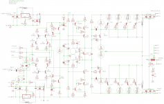
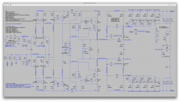
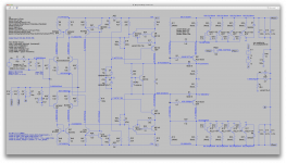
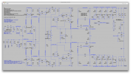
It's easily done. It's possible to increase the open loop gain and closed loop gain if needed, by changing parts values only. I'll adjust them in the attached schematic, though some will be experimental as discussed below.
We have a closed loop gain of about 30 now. Changing closed loop gain can be done easily by reducing the 249 ohm resistor R3 to a lower value, say 150. Gain is about 47 and input sensitivity increases 66%. Probably distortion increases by a similar amount, sorry to say.
We should review the open loop gain too, since increasing open loop gain may reduce closed loop distortion. The input and output stages have fixed gain. The input stage was limited to a gain of 10 by the local feedback from its output, to help with centering earlier. With the now improved NFB network, we can experimentally remove the two 680k resistors and verify centering. If nogo, add them back. Independently, we should reduce the input resistor to say 7k, which should make the offset less since it approximately matches the parallel resistance at the opposite side.
The DC gain of the output stage is fixed by the 39k resistive feedback to the driver base. The DC gain is quite high though, and tinkering with this resistor has caused other problems, so I don't see a win here. The AC gain of the output stage is greatly reduced by the huge Miller cap, 1n2, that we found necessary for stability. Once again, tinkering with that caused problems, so I'd hold off. We can reduce the 0.47 emitter resistors on the output transistors to 0.22 ohm to increase gain. We can possibly reduce the 4.7 ohm emitter resistor on the drivers for higher gain, if we can adjust bias and can still maintain centering. Try that in Spice and see what happens. Later we may consider making the LTP transistors into CFPs, if 150x more open loop gain is wanted.
Regarding increasing the supply voltage rails, this must be done with caution.
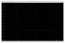
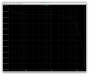
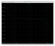
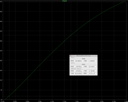
We must respect the safe operating area of the power transistors. Due to SOA limits, at higher voltages, output device current must be reduced by using more in parallel (simpler), or the output transistors must be cascoded to halve the Vce voltage (complex, but much more reliable). Either way we need 6-8 output devices at +-75v to be conservative. I've included a graph of SOA for these parts below. These devices do have excellent SOA compared to most other bipolar power transistors, but we still have to respect that limit diligently. Using 4 ohm loads, twice as many output devices would be needed, and we should have current sensing on the output devices with a smooth limiting function (in some future version).
It's easily done. It's possible to increase the open loop gain and closed loop gain if needed, by changing parts values only. I'll adjust them in the attached schematic, though some will be experimental as discussed below.
We have a closed loop gain of about 30 now. Changing closed loop gain can be done easily by reducing the 249 ohm resistor R3 to a lower value, say 150. Gain is about 47 and input sensitivity increases 66%. Probably distortion increases by a similar amount, sorry to say.
We should review the open loop gain too, since increasing open loop gain may reduce closed loop distortion. The input and output stages have fixed gain. The input stage was limited to a gain of 10 by the local feedback from its output, to help with centering earlier. With the now improved NFB network, we can experimentally remove the two 680k resistors and verify centering. If nogo, add them back. Independently, we should reduce the input resistor to say 7k, which should make the offset less since it approximately matches the parallel resistance at the opposite side.
The DC gain of the output stage is fixed by the 39k resistive feedback to the driver base. The DC gain is quite high though, and tinkering with this resistor has caused other problems, so I don't see a win here. The AC gain of the output stage is greatly reduced by the huge Miller cap, 1n2, that we found necessary for stability. Once again, tinkering with that caused problems, so I'd hold off. We can reduce the 0.47 emitter resistors on the output transistors to 0.22 ohm to increase gain. We can possibly reduce the 4.7 ohm emitter resistor on the drivers for higher gain, if we can adjust bias and can still maintain centering. Try that in Spice and see what happens. Later we may consider making the LTP transistors into CFPs, if 150x more open loop gain is wanted.
Regarding increasing the supply voltage rails, this must be done with caution.
We must respect the safe operating area of the power transistors. Due to SOA limits, at higher voltages, output device current must be reduced by using more in parallel (simpler), or the output transistors must be cascoded to halve the Vce voltage (complex, but much more reliable). Either way we need 6-8 output devices at +-75v to be conservative. I've included a graph of SOA for these parts below. These devices do have excellent SOA compared to most other bipolar power transistors, but we still have to respect that limit diligently. Using 4 ohm loads, twice as many output devices would be needed, and we should have current sensing on the output devices with a smooth limiting function (in some future version).
Attachments

Last edited:
You seem to be saying more gain is needed, to reduce input voltage requirements when using higher rails voltage. I certainly agree, and would aim for full output with input of say 1v RMS, or about 1.4v square wave. That's arbitrary, but it's low enough for most sources to drive to full output.
It's true the consumer aimed devices don't go quite as high in line level as the pro stuff. I guess it all depends on the type of usage that would be made of this, but I suspect it would be more suitable for P.A, with its lighter weight and smaller size. So if it's driven by a mix table or some equalizer, from the pro domain, then there isn't much to worry about. In case someone wanted to drive it using consumer type of device, then perhaps a little more gain would be helpful.
It's easily done. It's possible to increase the open loop gain and closed loop gain if needed, by changing parts values only. I'll adjust them in the attached schematic, though some will be experimental as discussed below.
The closed loop gain is the easiest to handle, and actually this could be decided at the build time by the diyer who makes it. A single resistor could set that gain.
As for the open loop gain, although I wasn't specifically saying it needed more, having done some torture tests lately, I do think it could use a little more.
I think it does have plenty in store to make available, but we don't want to go too far with that, just release a bit of gain mostly from the input stages, where feedback could be made a little bit weaker. There is no point in bothering with more gain in the output stages, it wouldn't make any difference anyway.
The principles of using local feedback on the inner stages to make a more moderate open loop gain should be sound, as devised by Matti Otala long ago, it's been done a lot since to reduce TIM. It wasn't specifically the goal here, but it goes along those lines. That local feedback here and there should make each stage more linear and stable, but maybe we don't need to tax the open loop gain quite that much.
This probably would help minimizing the thd and make the sine wave look still like sine waves in cases of hardship.
The type of torture tests that it's been subjected to has shown a tendency to distort when stressed.
I even added at some point a capacitor in parallel with the load, to see what happens on a capacitive load, and 100n is just fine, it makes no difference, but when going up only to 200n, that's when we can visually detect distortion and the peaks of the sine wave looks a little more like triangles than sines. Not huge, but we can see it.
Going beyond 200n on the output makes the signal degrade quickly.
I haven't tried yet the opposite reactive load that way, but it could be similar in behavior, although the simulated woofer load that I used at first has quite a bit of inductance in it, although this is not directly in series by itself, as it's a complex network with caps, coils and resistors to make it kind of like a real speaker.
There is no point in trying to simulate real speakers anyway, as simply halving the resistive load mostly imposes the same stress on the amp as any reactive complex load.
This may not be true for electrostatic speakers though, but who would use such things for P.A anyway?
We have a closed loop gain of about 30 now. Changing closed loop gain can be done easily by reducing the 249 ohm resistor R3 to a lower value, say 150. Gain is about 47 and input sensitivity increases 66%. Probably distortion increases by a similar amount, sorry to say.
Yes, but actually we don't really need to go that far. It's really not missing that huge of a gain. At 60V rails we've been driving it to full power just a tad before clipping with 1V6 and I only had to pump it up some more when I tried with the higher rails. Going from 60V to 75V is a fairly sizable increase, and that obviously took more input drive to get to full power.
Surely some diyers may even want to go higher than 75V rails, but then it's probably time to take a closer look at the SOA before committing to that.
We can probably improve a little here and there, besides the gain, to minimize distortion, and a little more open loop gain should allow even lower thd as well and probably better looking signal when stressed.
We should review the open loop gain too, since increasing open loop gain may reduce closed loop distortion. The input and output stages have fixed gain. The input stage was limited to a gain of 10 by the local feedback from its output, to help with centering earlier. With the now improved NFB network, we can experimentally remove the two 680k resistors and verify centering.
Yes, and maybe not remove completely. This needs to be compared.
I don't think that feedback is needed now for the centering, so it surely can be looked at for other reasons, such as controlling how much gain we want there for distortion reasons, and stability as well.
If nogo, add them back. Independently, we should reduce the input resistor to say 7k, which should make the offset less since it approximately matches the parallel resistance at the opposite side.
which input resistor are you referring to? The 33k at the in+?
The DC gain of the output stage is fixed by the 39k resistive feedback to the driver base.
That's the 33k that we've been using lately right? Not 39.
The DC gain is quite high though, and tinkering with this resistor has caused other problems, so I don't see a win here.
I agree. We've had many values tried and this seems fine as is right now. No need to break what already works. And I've been removing the network on the driver bases lately, which didn't do anything useful, and it's been fine that way too.
The AC gain of the output stage is greatly reduced by the huge Miller cap, 1n2, that we found necessary for stability. Once again, tinkering with that caused problems, so I'd hold off.
Yes. 1n looked ok at first, and then during stress it wasn't enough. Going higher brings nothing but more trouble, so 1n2 seems optimal right now.
We can reduce the 0.47 emitter resistors on the output transistors to 0.22 ohm to increase gain. We can possibly reduce the 4.7 ohm emitter resistor on the drivers for higher gain, if we can adjust bias and can still maintain centering. Try that in Spice and see what happens.
Yes, this shouldn't cause any big issues. We've had .22 on the emitters and dc operating points that worked before, even with lower driver emitter res as well.
I will try some values out and see what we get.
Later we may consider making the LTP transistors into CFPs, if 150x more open loop gain is wanted.
Actually I was just wondering if simply adding sziklai pairs on the existing ltp would suffice. Don't those bring the gain up and make for a more linear stage as well?
Regarding increasing the supply voltage rails, this must be done with caution.
We must respect the safe operating area of the power transistors. Due to SOA limits, at higher voltages, output device current must be reduced by using more in parallel (simpler), or the output transistors must be cascoded to halve the Vce voltage (complex, but much more reliable). Either way we need 6-8 output devices at +-75v to be conservative.
Of course. In spice there is no risk of blowing anything up and it won't even bark at SOA violations. That was just a test to see how it evolves, and besides a small bias adjustment, everything just works the same, with a higher input drive only.
Of course a closer look at SOAs would set maximum rail values for each number of pairs config. That could be something to do once it's stable and finalized, to give options to the builders.
I've included a graph of SOA for these parts below. These devices do have excellent SOA compared to most other bipolar power transistors, but we still have to respect that limit diligently. Using 4 ohm loads, twice as many output devices would be needed, and we should have current sensing on the output devices with a smooth limiting function (in some future version).
To make things simple, for an 8ohms version, we should test it for 4ohms, and it should be safe for the SOA that way, to handle any reactive situations.
For a 4ohms version, then tests should go down to 2ohms.
This is to stay on the safe side of things, within SOA in any case.
I don't think we really encounter any reactive loads as high as 45 degrees. Some people (paranoid) think they need to plan for 60 degrees, but I think that's overkill. Unless perhaps they drive electrostatic speakers, and then again, even those may not reach that much anyway.
We should do all we can to have let's say about 50 degrees of phase margin, and having at least 10db of gain margin is probably a good idea too.
For limiting, I've been thinking about using something different the usual, such as the type of limiter that is used in the likes of mcintosh amps.
Since we are using a fully symmetric input stage, we have a native differential input, that can be used to feed an opamp as they do in the mcintosh amps, and use that to limit the input signal, to prevent all clipping.
Although this isn't a true short circuit sensing system, it would detect it, because a short on the output with a signal driving it will automatically induce the type of distortion that is detected by such a setup on the input, and then limit the drive to keep it safe.
That is what mcintosh uses, and obviously it does work, well.
To be explored.
I just changed component values, since we have a working configuration. As you say, one resistor sets the gain. Just looking at what is possible to increase sensitivity since we had +-75. Adjustments as appropriate.
I am curious what effect changing the driver emitter load and its collector load had on the sloppy square wave. I am also curious if we still need the 680k resistors. Reducing the input resistor from 33k to 7K is an attempt to reduce offset voltage, may not be worthwhile since it's already low.
I prefer Szlikai pairs for the input. Self says they should reduce distortion by 10x theoretically, but seldom do in practice. They do add 4 actives, and could bring back some parasitic oscillations, so that's not to be done lightly. We do have stability finally, so changes make me wary. We might pick some matched low noise pairs too, if they are still made.
Regarding limiters, As you recall I had a Jfet acting as a automatic volume control when this started. We'll need something, with this high power. What I would like is nearly inaudible side effects from limiting, however we do it.
I just changed component values, since we have a working configuration. As you say, one resistor sets the gain. Just looking at what is possible to increase sensitivity since we had +-75. Adjustments as appropriate.
I went back to the 60V rails for the moment, and I will test with 75V next.
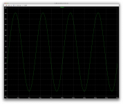
At the moment, with your latest values, and 60V rails, it looks rather good, although perhaps a little slow on those squares, but behaving neatly I think.
I put the load at 4ohms and even tried adding a cap on the output, in parallel with the load, and no effect can be seen up to 200n. We start seeing a small effect at 250n.
We apparently don't really need those 680k feedback, and with the input network as it is now, although a little more wasteful of input signal, the extra gain compensates a little and about 1V58 peak takes it just before clipping. At 60V rails.
This is quite acceptable even for consumer grade devices driving it, I think it should be possible for those to drive it to about full power on line level. or fairly close to it, which if the case, prevents over driving the amp as well.
I am curious what effect changing the driver emitter load and its collector load had on the sloppy square wave.
As you can see, it looks rather well behaved. Although maybe a bit on the slow side, there is no risk of overshooting and no hints of ringing whatsoever.
I am also curious if we still need the 680k resistors.
Does just fine without them. We're no longer fighting an imbalance, and it actually looks even better balanced now than earlier. We're at better than 1mV away from perfect balance.
Reducing the input resistor from 33k to 7K is an attempt to reduce offset voltage, may not be worthwhile since it's already low.
Just a tad more wasteful of input signal than before, but works very well and very nicely balanced now.
I prefer Szlikai pairs for the input. Self says they should reduce distortion by 10x theoretically, but seldom do in practice.
It prevents adding a full stage and shouldn't add as much extra effects as a full stage would, as far as I understand. They do boost gain, and I think improve linearity.
They do add 4 actives, and could bring back some parasitic oscillations, so that's not to be done lightly.
As long as we can manage the effects introduced and prevent instability, maybe they can help. But let's see what we get from what we have now. We may get satisfying results already, without adding more parts and complexity.
We do have stability finally, so changes make me wary. We might pick some matched low noise pairs too, if they are still made.
There are matched pairs in a single package that might be usable, in a DIP case for example, some may even have pairs with matched npn/pnp.
But as always, if all discrete, matching parts before building is a must.
Regarding limiters, As you recall I had a Jfet acting as a automatic volume control when this started.
Well, I've been researching this for some time and recently I've been seriously considering the mcintosh method.
I have been looking at options that prevent clipping, and act as a short circuit protection to avoid using the common VI limiters used in lots of amps. Those VI limiters are very difficult to make inaudible and there is always an unavoidable waste of SOA, because transistors don't turn on abruptly and if we want to make use of the maximum SOA, those limiters tend to start acting a little too early.
I prefer leaving the best chance to the amp to have an unimpeded function right until it actually reaches the clipping point.
The jfet option has been used in many commercial amps, and of course does work, but I find also that they do introduce some effects.
An other option that I feel may be less troublesome, is using vactrols instead of fets to do the limiting on the input. This seems to be less prone to introduce distortion, and although slower acting, it may be the best method, as far as I can tell, for now. I have not found any other method that can do better.
We'll need something, with this high power. What I would like is nearly inaudible side effects from limiting, however we do it.
Definitely, and in this topo, the use of VI limiters would be a little tricky anyway.
I think we can do better.
VI limiters only pretect the amp against shorts. They don't protect the speakers from overloading, especially from a clipping amp, and when over driven, the VI limters make the amp basically clip, which is very bad for speakers.
I think using the opamp to detect the signal degradation from whatever adverse use, wether it may be just over driving, a short on the output, an overly low load, or whatever, may just be the best solution, which negates the need for VI limiters and does all the protection needed, including the speakers themselves, in one shot.
That's why after looking at the various methods used out there, I have been leaning in favor of the mcintosh one, because it's non intrusive and only acts when there really is a reason to.
An amp protected that ways should be safe from shorts, and when over driven, it would never be allowed to clip.
This could be associated eventually with a solid state relay on the speaker output, to remove the speaker from the amp in case of real trouble. But even this may not be actually needed with this topo, because in fact, even in case of a catastrophic failure in any output device, the speaker is isolated from the rails by the big filter caps, which act as an inherent protection against any DC making it out to the speaker.
The worst the speakers could see in such extreme case is a huge transient, but no DC could be maintained on the output.
Attachments
looking pretty good so far.
60V rails
4ohms load
1V58 peak input signal
full power nearly 400W, right before clipping
with the latest values as is, no 680k feedback
Adding 200n in parallel on the output only adds a tiny bit of thd, not much
still stable
The higher noise figure compared to our earlier tests may be mostly due to the changes in the input network.
Attachments
-
 Screen Shot 2016-12-11 at 12.12.57 PM.png700.3 KB · Views: 63
 -
 Screen Shot 2016-12-11 at 11.55.20 AM.png226.8 KB · Views: 63
 -
 Screen Shot 2016-12-11 at 11.54.36 AM.png45.3 KB · Views: 60
 -
 Screen Shot 2016-12-11 at 12.18.05 PM.png47.2 KB · Views: 52
 -
 Screen Shot 2016-12-11 at 12.17.50 PM.png231.5 KB · Views: 59
 -
 Screen Shot 2016-12-11 at 12.20.36 PM.png227.1 KB · Views: 66
I expected the driver bias current to rise more than that when going with higher rails, but it's basically the same.
Anyway, at 75V rails, 2V drives it right to the edge of clipping, which we don't see on the wave plot, but we know it is at the onset by the thd starting to rise.
But hey, we're at 20khz and 4ohms.
And that amounts to well over 600Wrms.
But then SOA is highly likely violated, so better stay with 60V rails for now.
At 4ohms, we may even be in trouble with 4 pairs.
We'll know more when we try to plot some SOA...
Attachments

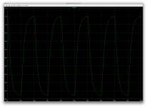
Here is what it does when clipping.
2V1 will make it clip, and the square wave clipping at 2V input confirms that it was clipping with the sine wave when driven with 2V peak, although we didn't really see that on the plot, the higher thd was a good hint.
It was out of headroom for sure.
So a pro device driving it at full line level (+4dbu) would be close to making it clip, but maybe not quite. It's not bad though, it's better to not over drive it, and very little headroom isn't used.
Clipping doesn't look too ugly. We do see that small hint of the little spike before the falling edge, as we had before, and it would grow when clipping even harder, but clipping is not normal, so there is no point it bothering to try to prevent that.
Sill, at 75V rails, SOA is likely violated with 4 pairs, so this is just to see what it does.
Attachments


Went back to 60V rails, and tried to change back the input network, at least partly, to see its influence on the noise figure.
Sill 4ohms load, and we should stay with that, aiming for a stable 8ohms amp on any load.
The noise figure goes down quite a bit with the input network at 1k/33k. I left the 22u input cap as is, which may not do much to noise anyway (only thd).
I'm sure most of the noise comes from that input network and the ltp with its current sources, but not much is to be worried about afterwards. I doubt the vas contributes too much to noise.
One thing is for sure, lowering the values at the input network may increase noise and waste more input signal, but it does balance the rails far better.
Attachments
On the falling edge, the slew rate looks about the same, so symmetric.
about 14V/us
input network still at 2k2/7k15
about 14V/us
input network still at 2k2/7k15
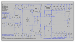
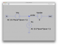
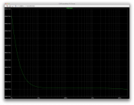
I tried inserting a tian probe to get a good phase and gain margin info, but results are inconsistent and don't make any sense.
We're supposed to be able to insert that probe anywhere inside the loop, and plotting should give the open loop gain, which doesn't look anything like what I think it is.
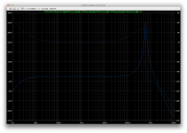
For one thing, the open loop gain should be far more than just a few db.
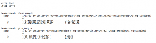
It does give a phase margin that somewhat looks possible, although insufficient. But we can't trust that.
Looking at what it says for gain margin confirms something just isn't right.
With this topology, we can't insert the probe at the amp's output and before the output coil and the feedback loop tap.
I tried putting it before the coil and after the middle point between the filter caps, and that should work, but same results.
Could someone with better understanding of tian's method help with this please?
We're supposed to be able to insert that probe anywhere inside the loop, and plotting should give the open loop gain, which doesn't look anything like what I think it is.
For one thing, the open loop gain should be far more than just a few db.
It does give a phase margin that somewhat looks possible, although insufficient. But we can't trust that.
Looking at what it says for gain margin confirms something just isn't right.
With this topology, we can't insert the probe at the amp's output and before the output coil and the feedback loop tap.
I tried putting it before the coil and after the middle point between the filter caps, and that should work, but same results.
Could someone with better understanding of tian's method help with this please?
Attachments
Trying to explore a little more the input filter in regards to the noise figure.
Looking for a compromise to minimize noise, get the best rail centering possible and waste as little input signal as possible.
The parallel input resistor hardly contributes to noise, but the series one does a great deal more, and to waste less input signal, we need the smallest series resistor possible and keep it as small as possible in regards to the one in parallel.
And since the lowest values for the parallel input resistor gets the best rail centering effect, we would tend to reduce them as much as possible, but then the filter cap from the R/C input filter would need to get huge, so a compromise is on order.
I see we had the cut off frequency at a little over 72khz with the 1n cap and that 2k2 res.
But with the 2k2 and 7k15 it's wasting a fair amount of input signal. And it does great rail centering, down to well below 1mV away from perfect.
So I figured perhaps a 470 series res with a slightly higher value for the parallel one, would not only improve the wasted signal issue, while keeping that parallel res low enough to keep the best centering we can get.
And this also means a 470 res needs a higher cap value. I figured we could use a 3n9 there, which brings the cut off frequency for the low pass at almost 87khz.
And then I tried a few values for the parallel res with that.
I tried from 6k2 and up to 18k, with 470 and 3n9.
Seems 10k might be a fair compromise. For very little wasted input signal, a rail balancing at some 2-3mV, which isn't bad at all, and the bandwidth is fine.
The thd isn't bad either (at 20khz/4ohms) and with 1V2 drive signal.
We're at over 350W on 4ohms resistive load already.
Can still be adjusted of course, but a possible compromise that works.
Attachments
-
 Screen Shot 2016-12-11 at 5.12.44 PM.png48.1 KB · Views: 52
 -
 Screen Shot 2016-12-11 at 5.09.48 PM.png186.1 KB · Views: 61
 -
 Screen Shot 2016-12-11 at 5.09.32 PM.png703.7 KB · Views: 49
 -
 Screen Shot 2016-12-11 at 5.11.09 PM.png291.8 KB · Views: 64
 -
 Screen Shot 2016-12-11 at 5.16.48 PM.png47.8 KB · Views: 57
 -
 Screen Shot 2016-12-11 at 5.17.34 PM.png225.7 KB · Views: 54
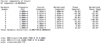
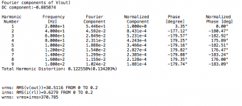
A few more quick readings on power and thd for 1khz, 200 and 20hz.
Load unchanged at 4ohms as previous readings.
I think the thd rising at lower frequencies can likely be improved a little by using larger caps.
Load unchanged at 4ohms as previous readings.
I think the thd rising at lower frequencies can likely be improved a little by using larger caps.
Attachments


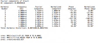
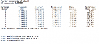
As I thought, increasing the caps brings down the thd a good amount.
Bringing the 22u to 47u drops it down some.
And then the 2200u to 4700u again drops it by about as much.
Big caps like that are common in good amps, such as bryston and others.
Good caps should be selected, and can help keeping thd low.
I didn't touch the big filter caps, but maybe they too could be a little bigger as well. But that's a more involved change.
Attachments
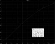
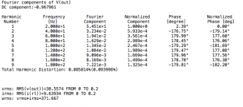
What the hell, why not trying the bigger filters as well.
I upped the 4700u to 6800u, and then 10000u.
thd gets better by a bunch more, and with 10000u and the input at 47u and feedback one at 4700u, we've halved the thd at 20hz.
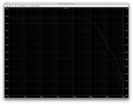
The ac plot shows a much flatter response at the low end of course.
It's a compromise for cost, but those who like their deep bass are certain to be favoring something like that.
I upped the 4700u to 6800u, and then 10000u.
thd gets better by a bunch more, and with 10000u and the input at 47u and feedback one at 4700u, we've halved the thd at 20hz.
The ac plot shows a much flatter response at the low end of course.
It's a compromise for cost, but those who like their deep bass are certain to be favoring something like that.
Attachments

- Status
- Not open for further replies.
- Home
- Amplifiers
- Solid State
- grounded collector amp