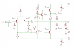
I don't like using zeners in audio circuits if I can avoid it and I can see no good reason why you've used one there. The diode next to it can go too IMHO. I like the 1k and 100u RC filter feeding the tail because its going to clean up all the hash and most of the hum on that rail. So why don't you just take a 47k resistor and connect it directly from the filtered rail to the LTP emitters and do away with that active CCS altogether? Sure it won't have the Meg ohm+ output impedance, but I bet that's not really helping that much, after all the collector load is quite high so the stage isn't going to generate much gain anyway.
I'd also get rid of the RC filter to the right, 220u and 100R - its redundant. You understand that the bootstrap is going to do a very good job preventing hum and hash injection at that point. Make C5 bigger if it makes you feel good, but its fine as is IMHO.
Edit; your C6 is still too small. If this were your "as built" schematic it would have blown up on the test bench.
Last edited:
I was downstairs listening to my workshop amp last night. It sounds real nice especially fed from a modest CRC linear supply and biased warm. R10 kinda goes against my philosophy because I generally like run these driver stages to ~20mA but this is all on a 2x2 inch pcb and I didn't have room for big onboard heatsinks.
Attachments
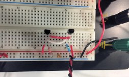
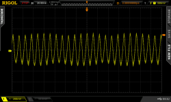
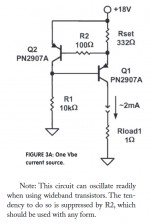
Here's an experiment I performed 15 minutes ago. The scope probe is connected to node OUT which is oscillating quite badly.People keep saying this [2T shunt feedback current sources oscillate] but I've never had a problem personally.
Q2 is on the left (emitter tied to VCC) and Q1 is on the right.
node EEE is the horizontal white wire
node BBB is the horizontal red wire
12K collector resistor (brown body) at left
154R emitter resistor (blue body) at right
0.1uF bypass capacitor, yellow body
The same circuit with the same component values is on a 2 layer PCB with ground pours, and it oscillates too. I copied it to the solderless breadboard seen here, to experiment with base stoppers. As you can see it oscillates on the solderless breadboard too.
Attachments
Thanks Hugh! Glad to hear it and congratulations.Mark, It (transistorized current source AND bootstrap capacitor) works well. Look over the 2011 FetZilla.
C6 has a huge impact on high frequency distortion. At 20khz, 0.018% to 0.033% if I increase it from 47p to 100p for example. I did move C6's right leg from the emitter of Q5 to the emitter of Q6.
This amp has to be fairly stable operating from a wide range of voltages. I haven't tried yet. Voltage regulation to the LTP, I thought, may help this. Perhaps just the CCS is enough.
My supply is an SMPS.
This amp has to be fairly stable operating from a wide range of voltages. I haven't tried yet. Voltage regulation to the LTP, I thought, may help this. Perhaps just the CCS is enough.
My supply is an SMPS.
Here's an experiment I performed 15 minutes ago. The scope probe is connected to node OUT which is oscillating quite badly.
Q2 is on the left (emitter tied to VCC) and Q1 is on the right.
node EEE is the horizontal white wire
node BBB is the horizontal red wire
12K collector resistor (brown body) at left
154R emitter resistor (blue body) at right
0.1uF bypass capacitor, yellow body
The same circuit with the same component values is on a 2 layer PCB with ground pours, and it oscillates too. I copied it to the solderless breadboard seen here, to experiment with base stoppers. As you can see it oscillates on the solderless breadboard too.
You made a pcb to test it?
I made a PCB to implement an amplifier and the first stage CCS oscillated like a mah forker. So I investigated further on the solderless breadboard.
Did u try placing a capacitor across collector and emitter to slow it down? Hopefully to DC.
I lol'd at a thought I just had. K.I.S.S. Keep It Stable Stupid.
This is not directed at you in any way. It was just twist on the old saying. 😀
I lol'd at a thought I just had. K.I.S.S. Keep It Stable Stupid.
This is not directed at you in any way. It was just twist on the old saying. 😀
Last edited:
Hi folks,
Found this thread interesting. Maybe this is off topic,
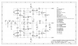
I bought an old Pioneer QX-9900 receiver of late and thought to sim up the old amp. It is an old bootstrap design. Any suggestions how to optimize this old design? I know many would say a complete re-design but lets see if we can improve this particular one.
What i did find so far, is if I used faster o/p devices,MJl3281/1302 it was fine, when I used slower MJL21194/5 it oscillated, so I increased the comp cap as shown.
attached is the ltspice sim I am using. Using modern day subs for original devices. Used Bob Cordell's models and vendors.
Found this thread interesting. Maybe this is off topic,
I bought an old Pioneer QX-9900 receiver of late and thought to sim up the old amp. It is an old bootstrap design. Any suggestions how to optimize this old design? I know many would say a complete re-design but lets see if we can improve this particular one.
What i did find so far, is if I used faster o/p devices,MJl3281/1302 it was fine, when I used slower MJL21194/5 it oscillated, so I increased the comp cap as shown.
attached is the ltspice sim I am using. Using modern day subs for original devices. Used Bob Cordell's models and vendors.
Attachments
Last edited:
Here's an experiment I performed 15 minutes ago. The scope probe is connected to node OUT which is oscillating quite badly.
Q2 is on the left (emitter tied to VCC) and Q1 is on the right.
node EEE is the horizontal white wire
node BBB is the horizontal red wire
12K collector resistor (brown body) at left
154R emitter resistor (blue body) at right
0.1uF bypass capacitor, yellow body
The same circuit with the same component values is on a 2 layer PCB with ground pours, and it oscillates too. I copied it to the solderless breadboard seen here, to experiment with base stoppers. As you can see it oscillates on the solderless breadboard too.
Hi Mark,
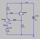
What if you put a 0.1uF capacitor between the collector and emitter of Q2?
Cheers,
Valery
Please circle that capacitor on the schematic of post #53?
There isn't one.
Hi folks,
Found this thread interesting. Maybe this is off topic,
I bought an old Pioneer QX-9900 receiver of late and thought to sim up the old amp. It is an old bootstrap design. Any suggestions how to optimize this old design? I know many would say a complete re-design but lets see if we can improve this particular one.
What i did find so far, is if I used faster o/p devices,MJl3281/1302 it was fine, when I used slower MJL21194/5 it oscillated, so I increased the comp cap as shown.
attached is the ltspice sim I am using. Using modern day subs for original devices. Used Bob Cordell's models and vendors.
It's not too off topic since I'm dabbling in the same thing, stability of a bootstrapped topology and optimizing distortion. Balance of the LTP and a low input impedance VAS has a significant impact on distortion. I can't view your file btw.
I encourage you to perform the experiment and report your findings here.What if you put a 0.1uF capacitor between the collector and emitter of Q2?
Below is a snip from Walt Jung's article "Sources 101"
_
Attachments
I had a 220 at the base at one point in time but I removed it because it had no effect (in emulation only).
Mark, do you still have your breadboard setup connected?
Mark, do you still have your breadboard setup connected?
SKA GB150D
Here's yet another amp using bootstrapping, Greg Ball's Simple Killer Amp, SKA GB150D.
http://www.diyaudio.com/forums/solid-state/238593-ska-gb150d-now-public-domain.html
Here's yet another amp using bootstrapping, Greg Ball's Simple Killer Amp, SKA GB150D.
http://www.diyaudio.com/forums/solid-state/238593-ska-gb150d-now-public-domain.html
Attachments
I encourage you to perform the experiment and report your findings here.
Below is a snip from Walt Jung's article "Sources 101"
_
Well, I know the result ))
I'm using this kind of arrangement with 2 x 2N5551, no base stopper and the cap across the voltage reference transistor. It never oscillates.
However, both Walt Jung and you are right for sure - wide bandwidth transistors must be used with caution here and both the base stopper and reference-shunting capacitor are the good things to have.
You have to read it with ltspice simulator.I can't view your file btw.
but i will attach a pdf if you are not familiar with ltspice.
Attachments
You have to read it with ltspice simulator.
but i will attach a pdf if you are not familiar with ltspice.
Increase C237. Mine is 47pf and I'm being told it's still too small. If I go to 22pf or 10pf I'll see ringing when injecting a square wave.
You can bypass R255.
What's up with R13? They have quiet a bit going on prior to the LTP.
I don't use LT Spice. I find it hard to read. Multisim looks more like a finished schematic. To me, it's much easier to read.
C237 was originally 15p, it was stable when I used MJL1302/3281
increased it to 22p, there was some peaking in the hi freq response, increasing C237 to 47p, removes this peaking, over compensated.
R13, I am not sure, does it force a lower input Z, 33K?
the printed schematic is in ltspice, you find my schematic hard to read?
increased it to 22p, there was some peaking in the hi freq response, increasing C237 to 47p, removes this peaking, over compensated.
R13, I am not sure, does it force a lower input Z, 33K?
the printed schematic is in ltspice, you find my schematic hard to read?
- Status
- Not open for further replies.
- Home
- Amplifiers
- Solid State
- Bootstrapped amps. DX/Aksa/RCA/etc...