Hi David,
My reply is a little late, but I agree with your take on the situations with cable installations. The workmanship here in Ontario isn't high quality, and the lack of a local ground connection is exactly what they don't do here. Maybe they should, but the actual installs I've seen are missing that connection.
Cable quality out here isn't good either. No surprise.
I sold a lot of 1:1 isolation transformers back in the day.
-Chris
This guy can probably help you. Worked at Brookdeal, his free book looks very nice and old school BTW.
https://sites.google.com/site/lockinamplifiers/home
Or the principle of this strange little company in the Channel Is.
EM D.C. PICOVOLTMETER MODEL P13 Specification.
This gets the no cigar award but will show you their basic design philosophy.
https://doc.xdevs.com/doc/_Legacy/Brookdeal/5003 NANOVOLT PREAMP.pdf
Thanks Scott for taking the trouble; I am going to ping this guy.
Jan
Hi David,
My reply is a little late, but I agree with your take on the situations with cable installations. The workmanship here in Ontario isn't high quality, and the lack of a local ground connection is exactly what they don't do here. Maybe they should, but the actual installs I've seen are missing that connection.
Cable quality out here isn't good either. No surprise.
I sold a lot of 1:1 isolation transformers back in the day.
-Chris
I surprised about the grounding. It written into the standards. The standards are the same as telco these days. I'm not surprised about the sloppy work of the installer. We have regular inspections. If it's not done right they go back on their time.
We had one guy, not an installer, wire up an apartment building and forget to install the ground. It was discovered a couple of years later when several TVs in the building had bad humbar. Oops. This time a power fault on the strand would have been negligence.
All of the faults from a cable system are caused from overhead power lines lighting up the strand or lightning strikes.
I got called out once for just this very thing to a commercial business. A power line fault put high voltage on the strand. The drop cable got so hot the PVC jacket liquefied and was dripping on the ground. I traced the damage to the cable box on the building where I found a ground block. The damage stopped there. There was no further damage past that point. The guy did lose all his fluorescent lighting ballast though. Not from the cable.
Because this was a so called act of nature it was an insurance matter.
Thanks Scott for taking the trouble; I am going to ping this guy.
Jan
Finding that free book on lock-in amplifiers was worth the trouble.
Finding that free book on lock-in amplifiers was worth the trouble.
Indeed - I need to read up also on those appendices. Brush up my understanding of all things noise.
This might be of interest to the LP crowd -- View attachment 583508
https://www.youtube.com/watch?v=RFKszehdmNs
-RNM
It would be interesting to bounce a laser off the spindle and compare to another TT.
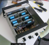
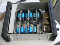
Inside of the Brookdeal 431. One would be tempted to think that three, at first sight identical, PC boards in a 60dB preamp would mean three boards of 20dB gain each.
But that's not optimal - for best S/N ratio we normally try to pack as much gain in the 1st stage as possible. So the plot thickens.
I like those big blue Philips electrolytics from the time I worked for them.
Probably all dried out by now, just like me 😛
Jan
But that's not optimal - for best S/N ratio we normally try to pack as much gain in the 1st stage as possible. So the plot thickens.
I like those big blue Philips electrolytics from the time I worked for them.
Probably all dried out by now, just like me 😛
Jan
Attachments
We could probably trace the circuit. .4nV at 20dB makes for a lot of drive into the feedback network. From the other schematic it's clear they were into paralleling FET's for noise. Couple of 8-BF862 <.4 nV circuits floating around here.
I have been using a Keithley 823 Nano-Volt amplifier/meter for decades. Fet input also. Never looked inside and dont have schematic. I ordered a manual for the 823. It has switchable gain to 1000 and LP and HP filters if needed can be switched in. Might be interesting if one could see the circuitry.
I dont think they paralleled the fets, though. If I need better, i can try paralleling.
Anyone else have or used one?
THx-RNMarsh
I dont think they paralleled the fets, though. If I need better, i can try paralleling.
Anyone else have or used one?
THx-RNMarsh
We could probably trace the circuit. .4nV at 20dB makes for a lot of drive into the feedback network. From the other schematic it's clear they were into paralleling FET's for noise. Couple of 8-BF862 <.4 nV circuits floating around here.
But in the use case for such an amplifier the voltage even after the first stage
is still pretty small, so the current into the fb network won't be too large.
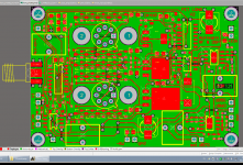
BTW I have redone the layout for my own preamp. I have now an active load
after the cascode that gain / bias current / supply voltage are more independent
and I get some better PSSR. It would have taken a 3nV/rtHz supply, which
I have but it is cumbersome.
I sent the Gerber/odb++ files in the night to Friday and may hopefully get the
boards before the next weekend.
While waiting for the mounting of my winter tyres on Friday afternoon I had the
laptop with me and found already the first minor bug 🙁 I should have slept
over it before pressing "send".
The feedback to the source takes care of the Cgs of the fets , the cascode is
effective against the Miller effect, but Cgd itself remains, especially with Vdd=3V.
I'd like to bootstrap the base of the cascode via an additional follower; when the
signal source is really low impedance one might get away with a coupling cap.
I also switch the gate resistor with an analog switch when the operating point
is badly wrong. That should speed up the waiting time after connecting to a
new measurement object. (lower corner is 0.1 Hz)
BTW in simulation I got a weird noise peak at 3 Hz when using the ADA4898
model instead of the OP37. I included another SO-8 socket in the layout
to be on the safe side; otherwise everything would fit into two 4898-2 pairs.
Are there op amp models out there in the wild with known-good noise modelling?
regards, Gerhard
Last edited:
I have been using a Keithley 823 Nano-Volt amplifier/meter for decades. Fet input also. Never looked inside and dont have schematic. I ordered a manual for the 823. It has switchable gain to 1000 and LP and HP filters if needed can be switched in. Might be interesting if one could see the circuitry.
I dont think they paralleled the fets, though. If I need better, i can try paralleling.
Anyone else have or used one?
THx-RNMarsh
The Brookdeal 431 also has a LP and HP switchable filter; an immediate use would be to make it less sensitive to mains hum.
Most of the transistors on the boards are 2N4126 which is not particularly low noise, and a BC184C which isn't either.
Now I'm really curious about the circuit!
Jan
BTW in simulation I got a weird noise peak at 3 Hz when using the ADA4898
model instead of the OP37. I included another SO-8 socket in the layout
to be on the safe side; otherwise everything would fit into two 4898-2 pairs.
Are there op amp models out there in the wild with known-good noise modelling?
regards, Gerhard
No idea, the macro models are usually plain text and open to being fiddled with. I hope they don't try to fit the noise to those bad graphs. 😉
Gerhard, is it for IF3602? 😉I included another SO-8 socket in the layout to be on the safe side
Gerhard, is it for IF3602? 😉
2 times IF3602 or 25 BF862 or similar, whatever is available.
Attachments
Thank you, I see that the integrator output is tied to gates and there is dc blocking input capacitor. If this capacitor is rolled (vs stacked) it works as a nice loop antenna for mains frequency and harmonics...
I had no problems with the caps; the version with 20 parallel op amps had 24 of them,
mounted dead bug style with hot glue because I could not get the smaller 10u/16V
for which the board was designed. That looks ugly and can never ever be photographed.
I suppose Wima knows how to build foil capacitors. I also tried 50V X7R with no
adverse effects such as microphonics but people kept warning, so I gave in.
The precursor is in #89621 of this thread, only with 16 BF862. Since the space was
available I increased that to 25. 😀
One can do a lot of interesting things with one's time if one avoids discussions
whether feedback works.
regards, Gerhard
One can do a lot of interesting things with one's time if one avoids discussions
whether feedback works.
regards, Gerhard
Ouch!
Last edited:
Are there op amp models out there in the wild with known-good noise modelling?
LME49860 (same as LME49710). It's a pretty accurate device level model (not a behavioural model) and includes the 1/f noise.
Probably all dried out by now, just like me
You should have been more thrifty with your surges, JD
(me, I've always been somewhat of a niggard)
Inside of the Brookdeal 431. One would be tempted to think that three, at first sight identical, PC boards in a 60dB preamp would mean three boards of 20dB gain each.
But that's not optimal - for best S/N ratio we normally try to pack as much gain in the 1st stage as possible. So the plot thickens.
I like those big blue Philips electrolytics from the time I worked for them.
Probably all dried out by now, just like me 😛
Jan
Those were nice caps. I bought them for the color and compact size.
- Status
- Not open for further replies.
- Home
- Member Areas
- The Lounge
- John Curl's Blowtorch preamplifier part II