Looks like somebody castrated a P-P amp to get a SE from it. ;-)
As the result, both triodes work on starved voltages. I would couple stages via a coupling cap, and biased both stages accordingly.
As the result, both triodes work on starved voltages. I would couple stages via a coupling cap, and biased both stages accordingly.
Looks like somebody castrated a P-P amp to get a SE from it. ;-)
As the result, both triodes work on starved voltages. I would couple stages via a coupling cap, and biased both stages accordingly.
Hi Wavebourn, as the resident GU50 expert, I was hoping you would join the party
Do you mind indicating on the schematic the modifications? Thanks
Hi Wavebourn, as the resident GU50 expert, I was hoping you would join the party
Do you mind indicating on the schematic the modifications? Thanks
It is not about GU-50, it is about 6SN7 tube
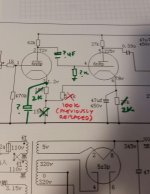
Put 2K resistors in cathodes of both triodes, and shunt them by caps.
Disconnect the grid of the 2'Nd triode from the anode of the 1'St one, and connect through a cap. And add a grid leak resistor there. Google for schematics with 6SN7 tube, as an example. Since you have a feedback, just replace the upper 150 Ohm by a 2K resistor with a cap in parallel.
Thanks. That will keep me occupied
Actually i have removed feedback...
...and what do you hear as the result?
What value should i use for the coupling cap and grid leak resistor?
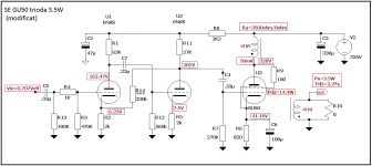
See attached. Is this correct?
See attached. Is this correct?
Last edited by a moderator:
Hello!
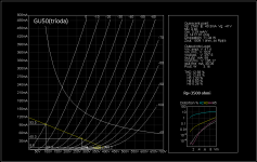
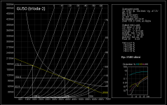
First, I think this configuration for your chosen PSF is not too good with FU50 tube (GU50) with another PSF can achieve much better performance without the presence NFB circuit electric. Images one can see the difference PSF between the two, especially on THD, harmonic distribution is the same in both cases, so the sound will not be altered but we gain in dynamics with a power output greater than, in my opinion!
In the images below you can see the shape and amplitude of the signal must have procedures for grid G1 final FU50 tube (GU50) .Input signal G1 (FU50) must be asymmetrical.
Attachments
Schematic attached again
Hi, can you tell me what PSF stands for?
What software did you use to model that info?
Thanks
Hi, can you tell me what PSF stands for?
What software did you use to model that info?
Thanks
Attachments
Last edited:
PSF = point static operation.
Uanod, Ianod, Ug1.
Sorry, I use abbreviations in Romanian language, sorry!
GU50 model was generated uTracer V3.0 and graphs were made with JavaScript Spice model generated uTracer on several real tubes.
Accuracy is very good, considering the rather large dispersion tubes actual parameters compared to the data catalog.
And a Spice model for GU50, if anyone's interested:
*********************************************
*@LMO
*uTracer 11 august 2016
*Vg2=250V
*russian data catalog
.SUBCKT GU50 1 4 2 3 ; P G2 G1 K (PENTODE)
.PARAMS: MU= 6.70 EX= 1.350 KG1= 1192.7
KP= 22.65 KG2= 10500 KVB= 55.0
CCG=15P CPG1=0.1P CCP=10.3P RGI=1K;
RE1 7 0 1G ; DUMMY SO NODE 7HAS 2 CONNECTIONS
E1 7 0 VALUE={V(4,3)/KP*LOG(1+EXP((1/MU+V(2,3)/V(4,3))*KP))}
; E1 BREAKS UP LONG EQUATION FOR G1.
G1 1 3 VALUE={(PWR(V(7),EX)+PWRS(V(7),EX))/KG1*ATAN(V(1,3)/KVB)}
G2 4 3 VALUE={(EXP(EX*(LOG((V(4,3)/MU)+V(2,3)))))/KG2}
RCP 1 3 1G ; FOR CONVERGENCE
C1 2 3 {CCG} ; CATHODE-GRID 1
C2 1 2 {CPG1} ; GRID 1-PLATE
C3 1 3 {CCP} ; CATHODE-PLATE
R1 2 5 {RGI} ; FOR GRID CURRENT
D3 5 3 DX ; FOR GRID CURRENT
.MODEL DX D(IS=1N RS=1 CJO=10PF TT=1N)
.ENDS
************************************************
Last edited:
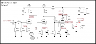
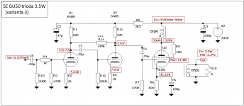
In the images below and see the original project but changed the project to which we applied a negative reaction Schade local type.
Try this out and maybe it will sound like.
My opinions and apologize for the inconvenience!
Try this out and maybe it will sound like.
My opinions and apologize for the inconvenience!
Attachments
Thanks Lazaroiu, I will give that a try
I have heard of Schade feedback but I need to read up on it to get a better understanding
Cheers
I have heard of Schade feedback but I need to read up on it to get a better understanding
Cheers
What value should i use for the coupling cap and grid leak resistor?
See attached. Is this correct?
In case you would decide to try it with feedback, I would suggest time constants of RC between stages at least 5 times different, to avoid oscillations on low frequencies.
Thanks Lazaroiu, I will give that a try
I have heard of Schade feedback but I need to read up on it to get a better understanding
Otto Schade proposed in his article back in 1938 a local feedback around 6L6 tubes, to make them more linear, with low output resistance, instead of using it in a dumb triode connection. He used a transformer based phase splitter to add a voltage feedback in series with an input signal. Here on the forum historically any local feedback around output tube is called by his name. For example, cathode feedback from the secondary, or a resistive feedback from anode to anode of the driver tube. If you want to try an anode to anode feedback, I would recommend you to use a pentode as a driver, instead of a double triode.
Name is a misnomer to say that this reaction Schade, but the effect is all linearization final stage of appeal tube.
We can apply a negative reaction "Schade" and between floors, the same effect of shrinking output impedance of the stage but linearization my opinion.
I have tried practically lot triode preamp floors, the effect was very clear Simiti change for the better sound and this due to excellent harmonic spectrum.
Anyway, basically try and eventually ear will tell if it is good or not, keep up the work!
Schade more accurately we can consider the configuration of the photo project:
Attachments
Why should we apply Shade's name to any feedback? Would not it bee too much? ;-)
Agree with you, say local NFB, in this case, would be more correct it?
Schade name to assign only one floor and NFB pentagrid final anode (tube end), anode tube pentagrid floor of attack (prefinal) would be more correct it?
You take into account so in future posts, thanks for the suggestion and to participate in discussions, it was an honor for me.
Speaking of a negative feedback.
There are current feedback and voltage feedback. Current feedback increases output resistance, voltage feedback decreases output resistance.
They can be applied either in series with input signal, or in parallel with input signal.
Series feedback increases input resistance, parallel feedback decreases it.
Thanks guys. I have a fairly basic understanding of amp design so more research and experimentation to come
Its interesting that the amp sounds so good as it is. Is it a characteristic of this tube to have a very 3 dimensional presentation of the sound stage? Ive not had this with any other amp and I have used ss, tube, Tripath etc.
Its interesting that the amp sounds so good as it is. Is it a characteristic of this tube to have a very 3 dimensional presentation of the sound stage? Ive not had this with any other amp and I have used ss, tube, Tripath etc.
- Home
- Amplifiers
- Tubes / Valves
- FU50 tube amp mods and schematic