Hi!
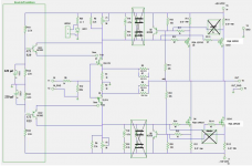
I got a problem with my f5 turbo v1 build.
I use cascoding transistors bc550 bc560.
I messaure 0,38v around the 0.5 ohm Source resistors, 32v rails, 15 v from the bc550 and current limiting (ztx550 ztx 560).
Double mosfet output messaure 0v on the gate.
I can play music but not very loud.
The problem is that the mosfet not working, no heat from them.
The jfet seems to work.
how should i solve the problem?
any idea?
0.38V across 0r5 resistors indicates that 760mA is passing.
That is your bias.
It should be the same for both source resistors, if your output does not have a load.
±25Vdc and 760mA of bias results in a dissipation of 38W.
±32Vdc for an F5t gives a dissipation of 48W per pair.
Something has to be getting hot !
That is your bias.
It should be the same for both source resistors, if your output does not have a load.
±25Vdc and 760mA of bias results in a dissipation of 38W.
±32Vdc for an F5t gives a dissipation of 48W per pair.
Something has to be getting hot !
your math is right.
When i switch on the receiver with a 200 w bulb limiter, the bulp light up for
a 5 sec. after 10 min the mosfets it's still cold, but i can play music very softly.
When i switch on the receiver with a 200 w bulb limiter, the bulp light up for
a 5 sec. after 10 min the mosfets it's still cold, but i can play music very softly.
across the resistors.
r2 0,050v
r4 3,48v
r6 0,22v
r12 0.3v
r10 0.005v
r14 0v
r22 31,2v
r2 0,050v
r4 3,48v
r6 0,22v
r12 0.3v
r10 0.005v
r14 0v
r22 31,2v
Attachments
Last edited:
Voltages measured across the resistors or referenced to ground? 3V across R12 is 6A. That makes no sense that there's not a lot of heat somewhere if that is the case.
Have you measured R11 as well? How about DC offset of the output? I suspect that you have a bunch of offset dialed in (causing the R12 reading relative to ground) but have not yet biased the output stage into conduction. Remember it's an iterative process, fixing offset will knock the bias back so go back and redo your biasing procedure again.
Have you measured R11 as well? How about DC offset of the output? I suspect that you have a bunch of offset dialed in (causing the R12 reading relative to ground) but have not yet biased the output stage into conduction. Remember it's an iterative process, fixing offset will knock the bias back so go back and redo your biasing procedure again.
I found the problem!
😱😱
I got wrong value on the source resistor 50 ohm instead of 0,5 ohm.
0.3V / 50Ohms = ~ 0,006A
It's explain no heat on the mosfet,!!
😉😉
😱😱
I got wrong value on the source resistor 50 ohm instead of 0,5 ohm.
0.3V / 50Ohms = ~ 0,006A
It's explain no heat on the mosfet,!!
😉😉
Aha! Good job spotting the error! Sometimes it's very difficult to see when it's your own work.
my problem with my amp...hum...the rectifier stage is buzzing. at least it seems the buzz comes from it.
need some advice to solve it.
need some advice to solve it.
An externally hosted image should be here but it was not working when we last tested it.
An externally hosted image should be here but it was not working when we last tested it.
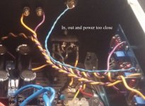
Even though they are twisted get those power cables away from the signals.
Cross cables at 90deg not parallel and strap the power cables low down to the base of your cabinet.
Cross cables at 90deg not parallel and strap the power cables low down to the base of your cabinet.
i think this is what you are talking about. the power cable that goes into the amp is going down to the chassis
An externally hosted image should be here but it was not working when we last tested it.
yes, agree. in this last pic i tried to put them wider.
one other question regarding the arta measurements - i am measuring with an 8ohm load and a 100k pot with a 10uf cap in the output. i am regulating the pot to 2.83vac, wich i think its 1watt. is it right? do you also consider the vrms output to measuring?
one other question regarding the arta measurements - i am measuring with an 8ohm load and a 100k pot with a 10uf cap in the output. i am regulating the pot to 2.83vac, wich i think its 1watt. is it right? do you also consider the vrms output to measuring?
now...a little better...but far away from a good result
i reduce the noise by tightning the bolts on the diode heatsinks.
i reduce the noise by tightning the bolts on the diode heatsinks.
An externally hosted image should be here but it was not working when we last tested it.
Your FFT measures the 50Hz @ 60dB below your signal.
What does the 50Hz measure using a DMM when the input is shorted?
What does the 50Hz measure using a DMM when the input is shorted?
now...a little better...but far away from a good result
i reduce the noise by tightning the bolts on the diode heatsinks.
An externally hosted image should be here but it was not working when we last tested it.
Hmm, depending on the measurement setup, the 50 Hz peak could be anything. How did you measure this (with a soundcard, cables, etc.)? What's the 50 Hz in a "blank" measurement (testing at the output of the signal generator, where it would be connected to the amp input)?
Without signal generator there is no 50hz hum.
I have 0.3-0.4 mv with inputs shorted.
Measurements made with maudio ap192 and a probe box with 100k pot and 10uf cap
I don't know what to do more. The ixis diodes keeps buzzing. I've tightened them and separate them apart the PCB and now i have them both sides of the toroid. I don't want to give up on them and go for monolythic ones because they were expensive. But if i have to...
this is Hum + Noise. The noise portion with a shorted input should be very low. That leaves the majority of the measured 0.3mVac to 0.4mVac as the hum. It is not zero hum ! It is low level hum.Without signal generator there is no 50hz hum.
I have 0.3-0.4 mv with inputs shorted.
It looks like it's your measurement system that is being contaminated by the way you are wiring up the measurement system.Measurements made with maudio ap192 and a probe box with 100k pot and 10uf cap
I don't know what to do more. The ixis diodes keeps buzzing. I've tightened them and separate them apart the PCB and now i have them both sides of the toroid. I don't want to give up on them and go for monolythic ones because they were expensive. But if i have to...
Can you see where that contamination is getting in?
Can you short the input signal at the amp input while all the measurement system is still connected and see what difference that makes to your results?
this is Hum + Noise. The noise portion with a shorted input should be very low. That leaves the majority of the measured 0.3mVac to 0.4mVac as the hum. It is not zero hum ! It is low level hum.It looks like it's your measurement system that is being contaminated by the way you are wiring up the measurement system.
Can you see where that contamination is getting in?
Can you short the input signal at the amp input while all the measurement system is still connected and see what difference that makes to your results?
I will do that, but i think that's not the problem. when i have my amp conected to my 89db tannoy sensys, i can hear the buzz or hum.
- Home
- Amplifiers
- Pass Labs
- F5 Turbo Builders Thread