That looks to be a good value. Read the AC specs carefully. They are good but not exceptionally good and could be misleading if you are obsessing over frequency response. The almost 6 digits in a handheld is impressive. My first 6-1/2 digit meter was 2 RU and 24" deep. This is almost as accurate and probably 1/100 the original retail.
The rising noise floor of the ESI ADC is characteristic of most sigma delta ADC. The ESI uses the AK5385 (same as the RME HDSP9624) which has that rise. Its the noise shaping.
In my experience when chasing really low levels you need a single ground connection between the source and the measurement chain. I usually have several clip leads and just try connections until I get the lowest noise. The power line noise can be most vexing. Its usually leakage through a power transformer or power supply. Sometimes tieing the shield or case to the soundcard chassis with a clip lead shunts the current before it gets mixed with the signal you are looking at. Also just moving away from the bench can make a difference. There are magnetic fields from power cords and transformers that are small except when you are looking below -130 dBV.
In my experience when chasing really low levels you need a single ground connection between the source and the measurement chain. I usually have several clip leads and just try connections until I get the lowest noise. The power line noise can be most vexing. Its usually leakage through a power transformer or power supply. Sometimes tieing the shield or case to the soundcard chassis with a clip lead shunts the current before it gets mixed with the signal you are looking at. Also just moving away from the bench can make a difference. There are magnetic fields from power cords and transformers that are small except when you are looking below -130 dBV.
Can you repeat that with a 60 Ohm resistor (2*120 par)? = 1nV/rtHz
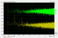
Attached, yellow is when input was shorted, green is when connected to a pair of 120R resistor (that measured 59R8 combined). The LNA is still not in a chassis, but I put the whole stuff in a grounded cookie can so there is less 50Hz pickup this time.
What I said myself in this thread and elsewhere... 10Hz corner frequency is out of this world.

Probably a typo in the article. Anyway, what concerns me most is the noise I measured - 390pV/rtHz at high frequency, 500pV/rtHz at 10Hz, which is the same as what's shown on Fig.14 🙂
Attachments
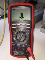
(Recommendations on quality DMMs that don't cost the earth appreciated.)
I have been using the Brymen BM869s (that Mark ordered) and I like it very much, despite having a more expensive bench top DMM, I always prefer the Brymen unless I have to do 4-wire resistor measurement.
One thing to note is that the battery drains relatively fast, in around 2 years of use I had to replace it twice already, and the fuse is a little hard to find when you burn it (I learnt it the hard way).
Attachments
And, if I may, what noise do you measure with the input to the preamp open circuit?
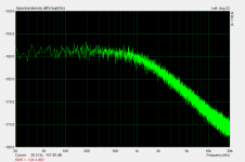
I'm not sure what's the meaning of this measurement, but this is what I got.
Attachments
Last edited:
Probably a typo in the article. Anyway, what concerns me most is the noise I measured - 390pV/rtHz at high frequency, 500pV/rtHz at 10Hz, which is the same as what's shown on Fig.14 🙂
According to this "exchange", it is not a typo:
http://www.diyaudio.com/forums/equi...r-audio-vol-3-spare-boards-9.html#post4721471
Note the author mentioning he did not sort the jfets for LF noise, but for other (unclear to me) reasons.
I have no big problem with the HF noise performance, 0.4nV/rthz from 8 jfets running at 1mA is about what I would expect, on the optimistic side.
I'm not familiar with 1/f noise at all, but I want to get my head clear on this topic so I Google a bit, one of the result is this:
1/f Noise?the flickering candle | EDN-
Please excuse me if what I'm going to say is stupidly wrong, but from the above link, the definition of 1/f corner frequency is:
"Amplifier noise is a combination of 1/f noise and flat (white) noise. The flat noise continues at low frequency but 1/f noise dominates (figure 2). The 1/f noise continues at high frequency but flat noise dominates. The two blend at the corner frequency, adding randomly to make a 3dB increase."
With this LNA, the flat noise is 390pV/rtHz, so the amplifier noise at the 1/f corner frequency will be 552pV/rtHz (3dB increase). Since the measured noise at 10Hz is 500pV/rtHz only, it follows that the 1/f corner frequency is below 10Hz.
It seems quite a fair statement to say that the 1/f corner frequency of this LNA is below 10Hz.
It would appear that for me to reliably use the sound card as the stimulus I would need to purchase a very good quality voltmeter/DMM in order to calibrate the output volume. I don't think I can rely on my free UNI-T UT120A. (Recommendations on quality DMMs that don't cost the earth appreciated.)
Parts Express has the Keithley 6.5 digit wideband 2015 dmm for 349 - retail used to be 4000....
End of line; I got two.
Jan
The rising noise floor of the ESI ADC is characteristic of most sigma delta ADC. The ESI uses the AK5385 (same as the RME HDSP9624) which has that rise. Its the noise shaping.
In my experience when chasing really low levels you need a single ground connection between the source and the measurement chain. I usually have several clip leads and just try connections until I get the lowest noise. The power line noise can be most vexing. Its usually leakage through a power transformer or power supply. Sometimes tieing the shield or case to the soundcard chassis with a clip lead shunts the current before it gets mixed with the signal you are looking at. Also just moving away from the bench can make a difference. There are magnetic fields from power cords and transformers that are small except when you are looking below -130 dBV.
... and that's why every household should have a couple of SilentSwitchers 😀
Jan
The Brymen looks like a good purchase. Quite a bit cheaper than the Fluke 179.
Jan, did you mean the refurbished ones at Parts Connexion? I couldn't find them at Parts Express. DMM Digital Multi Meters
Jan, did you mean the refurbished ones at Parts Connexion? I couldn't find them at Parts Express. DMM Digital Multi Meters
The Brymen looks like a good purchase. Quite a bit cheaper than the Fluke 179.
Jan, did you mean the refurbished ones at Parts Connexion? I couldn't find them at Parts Express. DMM Digital Multi Meters
Yes. I'll see if I can find the link. They also advertising tie here at diyaudio.
£282 from Farnell !The Brymen looks like a good purchase. Quite a bit cheaper than the Fluke 179.
Jan, did you mean the refurbished ones at Parts Connexion? I couldn't find them at Parts Express. DMM Digital Multi Meters
So I bought a Tenma 72 2600 for £35 from CPC.
I'm not sure what's the meaning of this measurement, but this is what I got.
Not dissimilar at LF to what I got.
According to Waly here
I haven't seen the schematic, but something is fishy here. If the open input noise is -160dB (at LF), it means that the input impedance (creating that noise at LF) is about 6500 ohm (10nV/rtHz).
But an input impedance of just 6.5kR doesn't gel with the schematic or spec of the preamp.
The rising noise floor of the ESI ADC is characteristic of most sigma delta ADC. The ESI uses the AK5385 (same as the RME HDSP9624) which has that rise. Its the noise shaping.
In my experience when chasing really low levels you need a single ground connection between the source and the measurement chain. I usually have several clip leads and just try connections until I get the lowest noise. The power line noise can be most vexing. Its usually leakage through a power transformer or power supply. Sometimes tieing the shield or case to the soundcard chassis with a clip lead shunts the current before it gets mixed with the signal you are looking at. Also just moving away from the bench can make a difference. There are magnetic fields from power cords and transformers that are small except when you are looking below -130 dBV.
I'm struggling to believe grounding can be the cause of a lack of measured 20dB per decade roll-off in PSRR of a voltage regulator DUT. I think what I noticed with measuring the output of the amp was coincidentally similar and nothing more. When the preamp enclosure was grounded it merely brought the lower frequency background noise down to that of the higher frequency. But maybe I'm wrong.
I had 'knee-jerk' defaulted to using the balanced side of the Juli@ XTe, relying on the shield/pin 1 being connected to chassis and the card/computer end as well as at the source end (where I have pin 1 tied to the enclosure of the preamp or have been clipping pin 1 to the enclosure of other single-ended devices I've attempted to measure). Inputs to a balanced connection need not be symmetrical. But as I think about using it as a stimulus as well, perhaps it makes sense to use the single-ended RCA connections (although still with dual conduit cable) as presumably it would output a symmetrical signal via pins 2 and 3 which might be poorly received by a single-ended device.
Balanced uses pins 2 (hot) and 3 (cold) for signal. Pin1 is screen and chassis/enclosure.I'm struggling to believe grounding can be the cause of a lack of measured 20dB per decade roll-off in PSRR of a voltage regulator DUT. I think what I noticed with measuring the output of the amp was coincidentally similar and nothing more. When the preamp enclosure was grounded it merely brought the lower frequency background noise down to that of the higher frequency. But maybe I'm wrong.
I had 'knee-jerk' defaulted to using the balanced side of the Juli@ XTe, relying on the shield/pin 1 being connected to chassis and the card/computer end as well as at the source end (where I have pin 1 tied to the enclosure of the preamp or have been clipping pin 1 to the enclosure of other single-ended devices I've attempted to measure). Inputs to a balanced connection need not be symmetrical. But as I think about using it as a stimulus as well, perhaps it makes sense to use the single-ended RCA connections (although still with dual conduit cable) as presumably it would output a symmetrical signal via pins 2 and 3 which might be poorly received by a single-ended device.
The pin2 to pin3 signal is a differential signal and can be read by both single ended inputs and by differential inputs.
It does not matter that the signal voltage on Pins 2 & 3 are a different value. It's the difference between them that is the signal.
Even in a true balanced impedance connection, the difference signal does not require that the two signal pins have equal values of voltage. They just need to be different, the differential input reads/measures the difference and processes that as the signal..
Last edited:
Yes but I was a bit more nervous about the case of balanced output sinus (where pins 2 and 3 are symmetrical) to single ended. In this case one is banging the single-ended circuit's ground around. Perhaps this isn't an issue.
(The other way clearly isn't an issue as the differential input signal need not be symmetrical. My implementation of Self's low noise balanced to single-ended board simply connects the single-ended RCA directly to pins 2 and 3 of the balanced input.)
(The other way clearly isn't an issue as the differential input signal need not be symmetrical. My implementation of Self's low noise balanced to single-ended board simply connects the single-ended RCA directly to pins 2 and 3 of the balanced input.)
The "balanced output" of this preamp isn't truly balanced, J102-4 is just GND floated by a 51R resistor.
I take the SE output from pin 2 and pin 5 (GND) of J102, and feed it into pins 2 & 3 of the XLR input of my soundcard, that gives the best results in my case.
I take the SE output from pin 2 and pin 5 (GND) of J102, and feed it into pins 2 & 3 of the XLR input of my soundcard, that gives the best results in my case.
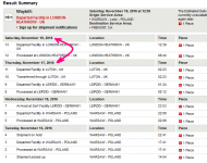
Argh, Brymen multimeter is stuck in UK bureaucracy it seems. 3 days to meander from one London airport to another.
Attachments
Last edited:
Argh, Brymen multimeter is stuck in UK bureaucracy it seems. 3 days to meander from one London airport to another.
That's to be expected, Luton airport is for to/from Europe destinations, Heathrow is the hub for flights over the pond. And don't count Sat as a day, processing was done on Fri.
Last edited:
The "balanced output" of this preamp isn't truly balanced, J102-4 is just GND floated by a 51R resistor.
If the impedance on the other line is also 51 ohms, that is truly balanced. Then the impedances are equal which is the criterion.
Jan
- Home
- Design & Build
- Equipment & Tools
- Groner's Low noise measurement amp from Linear Audio vol 3 - spare boards?