That's why I think Bob's sim of a wide array of subs looked good.
It also has to do with the relatively close center to center spacing in that sim. Those are big subs but still the center to center distance is only 4 feet from each sub to it's neighbor.
OP's suggested center to center spacing with only two huge horns side by side is much larger and as you noted with only the two subs the interaction is much less complex than with a long line of subs so there's much less averaging effect and much deeper and wider notches.
That is nicely put, and much more clear than your earlier response (post 808).At very low frequencies localization is very difficult and below the crossover point of 80 hz that I've suggested it's nearly impossible if the slope is steep and the sub is very low distortion.
At high frequencies localization is very easy.
That is why you need a very large separation if you want any chance at all of perceiving stereo bass but relatively little separation to perceive separation at mid/high frequencies.
You used "they [plural] aren't far enough apart" - which seemed to reference the location of the mains (plural), since I had referred to the (singular) bass array & illustrated the cells of my suggested bass layout as being monolithic - the L and R channels would be no distance apart.
Putting aside stereo bass, an array would have the other benefits you snipped earlier - more control (delay, the ability to run some drivers over a wider range than others), plus others: smaller spans = stronger/easier structurally and 1 or 2 drivers per throat = better than 4 or 8, for experimenting with higher crossovers, as the OP wishes.
You even said yourself "I don't think that, with a blindfold on, you could play an 80Hz tone through a line of 12 of these boxes, and point to each of the 24 woofers or "centers".
This implies two things.
1. Why bother with stereo bass if you can't localize it well?
2. If you can't point directly at the sub when blindfolded, it's going to be even harder to point at it when it's relatively close to another sub.
You truncated that and butchered the intent. Why bother? It's not like I'm going to nod sagely and agree.
The DBH218 that Bob used in his model is a folded horn using 2x18" woofers. I don't think that, with a blindfold on, you could play an 80Hz tone through a line of 12 of these boxes, and point to each of the 24 woofers or "centers". I think the whole mouth would be the source.
Even without the blindfold, you couldn't point to the woofers in that specific box, because the woofers are buried in folded horns. That's why I think it is daft to model them as point sources. If the ground and horn were made of mirrors, you'd see a jillion images of each woofer. Would the pictured object be point sources?
Attachments
You truncated that and butchered the intent. Why bother? It's not like I'm going to nod sagely and agree.
Sorry, that was not the intent. I always try to snip quotes to the bare essentials. I didn't think any more was necessary since you wrote it and you knew what you meant when you wrote it.
Even without the blindfold, you couldn't point to the woofers in that specific box, because the woofers are buried in folded horns. That's why I think it is daft to model them as point sources.
I said it before - Danley Direct is what DSL uses to set their very complex systems up. I have no idea what's baked into that software - maybe they use point source maybe not, maybe diffraction too. Maybe they use actual polar measurements, I have no idea and there's no instructions so it's vague at best.
But if DSL uses it to good effect it can't be bad at it's job.
The PCD software I was using early on because I had never used Direct. Then more recently I used it since it allowed the sim to show offset in all 3 dimensions and allowed a 300 hz crossover point (I'm not sure if any of the DSL subs will go that high).
And the PCD software agrees reasonably well with Direct - I haven't done a head to head comparison of the exact same setup with both programs but they both clearly showed the same 20 db notches two octaves wide in the bass.
If it makes everyone happy I won't use the PCD software anymore for examples, only Direct, even though they seem to agree pretty well. I don't think anyone is going to argue that Direct is so flawed that it's useless. The only thing it can't do properly is the directivity of a huge horn which is no consequence as long as the intended audience position is fully inside the horn beam. And maybe the wavefront shape of the DSL subs isn't exactly perfectly matched to OP's horn either, but it makes little difference, it will just change the pattern slightly.
The Direct software takes the polar plot of the TEF measured speakers and subs then taking into account the physics behind wave propagation they make plots
Quote:
Originally Posted by just a troll:
A multicell horn is not the same as side by side massive subwoofers.
Exponential multi-cell horns behave nearly identically regardless of the size, with a few notable distinctions listed below.
Regardless of size, the acoustical point of origin located at the horn throat of each cell must be located within 1/4 wave length of adjacent cells for the upper pass band to "seamlessly" sum with adjacent cells. The acoustical points of origin must describe the central axis of the arc the cells describe.
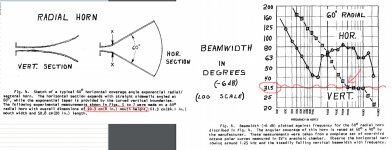
Although exponential multi-cell HF can sound excellent, and somewhat solve the HF "beaming" dispersion problems of a single cell radial exponential, they are a trade off of multiple HF "fingers" vs vertical beaming. Choose your poison between those two, or use any of the many "constant directivity" horn designs, each with their own sonic compromises.
Audio choices would be so much easier if you could make them simply by looking at pictures,or graphs, rather than actually listening to the different devices in the myriad configurations that attempt to reproduce, or create sound.
1) At HF (high frequencies), sound waves tends to propagate like beams of light, "ray tracing", reflecting from any surface, and HF is hard to hear (being many dB down) when you can't see the horn's throat. "Overlap" of adjacent HF cell output will cause HF "fingering" or "comb filtering".
2)At LF (low frequencies) sound tends to propagate like a liquid's laminar flow, flowing around cabinet bends, unimpeded, like water through a coiled hose. "Overlap" of adjacent cell's output will generally be below the upper pass band chosen for a "sub", so the individual "cells" or drivers, or horns, will "seamlessly" contribute to the output, if the acoustical points of origin describe the central axis of the arc the cells describe.
Ain't sound fun?
Cheers,
Art
Originally Posted by just a troll:
A multicell horn is not the same as side by side massive subwoofers.
Hollowboy,Correct. Subwoofers are bigger.
The OP was talking about dividing a single horn into 4 parts with same length & abutting mouths. That seems to have more than a casual resemblance to a multicell.
Exponential multi-cell horns behave nearly identically regardless of the size, with a few notable distinctions listed below.
Regardless of size, the acoustical point of origin located at the horn throat of each cell must be located within 1/4 wave length of adjacent cells for the upper pass band to "seamlessly" sum with adjacent cells. The acoustical points of origin must describe the central axis of the arc the cells describe.
Although exponential multi-cell HF can sound excellent, and somewhat solve the HF "beaming" dispersion problems of a single cell radial exponential, they are a trade off of multiple HF "fingers" vs vertical beaming. Choose your poison between those two, or use any of the many "constant directivity" horn designs, each with their own sonic compromises.
Audio choices would be so much easier if you could make them simply by looking at pictures,or graphs, rather than actually listening to the different devices in the myriad configurations that attempt to reproduce, or create sound.
1) At HF (high frequencies), sound waves tends to propagate like beams of light, "ray tracing", reflecting from any surface, and HF is hard to hear (being many dB down) when you can't see the horn's throat. "Overlap" of adjacent HF cell output will cause HF "fingering" or "comb filtering".
2)At LF (low frequencies) sound tends to propagate like a liquid's laminar flow, flowing around cabinet bends, unimpeded, like water through a coiled hose. "Overlap" of adjacent cell's output will generally be below the upper pass band chosen for a "sub", so the individual "cells" or drivers, or horns, will "seamlessly" contribute to the output, if the acoustical points of origin describe the central axis of the arc the cells describe.
Ain't sound fun?
Cheers,
Art
tl;dr version: a midrange multicell measures better than it "should", so I think a bass array would too.
Each individual cell of that EV multicell (assuming a 30 degree angle and a 20cm mouth), would lose pattern control below ~5kHz (see my links in post 472, or page 7 of Keele's paper). Below 5kHz, the outputs of 20cm mouths will overlap substantially, whether they are parallel or splayed out "a few degrees".*
The range below 5Hz, where the outputs overlap substantially, is where the horn performs best.
The Audio Xpress article says this loss of control is known/intentional "the multicellular horn is a cluster of smaller exponential horns, each with a mouth small enough to avoid beaming in a large frequency range"**
...so splaying & beaming cannot be the explanation, since the cells are not beaming over the horns 'good' range.
Figure 15, shows a ~flat wave-front, where the exponential horn is operating at 7x the cutoff frequency. You skipped over this point when snipping my post. If the OP builds a 15Hz horn, 100Hz will be 7x his cutoff frequency.
Later figures (18 and onward) are for tractrix and other horns. Given that "The main assumption in the tractrix horn is that the sound waves propagate through the horn as spherical wave-fronts", it is not shocking that the article shows spherical wave-fronts for them. The article also notes that the spherical thing can only "come close at low frequencies".
I was picking up from the OP's speculation about the opposite shape (example 1, post 784) - an array of 4 long bass horns, each
"only" 8' wide. The side walls of such a horn would be a lot closer to parallel than the horn in David McBean's example. A wave-front that was normal to a relatively flat wall should also be relatively flat.
I've simmed a 15Hz horn at 100Hz, with HR, and am not at all surprised to see that the wavefront at the mouth is pretty flat.
Again: "always" is the wrong word. It doesn't apply in the specific case the OP was speculating on.
**so presumably having smaller mouths (and more of them) would push the "fingering" pattern up to a higher frequency.
Nope.If they were all pointed directly ahead (in the same direction) this would be true. But they are not, they are splayed out, each pointing a few degrees away from the next. This goes a long way to reducing the interference of a narrowly beaming horn array.
Each individual cell of that EV multicell (assuming a 30 degree angle and a 20cm mouth), would lose pattern control below ~5kHz (see my links in post 472, or page 7 of Keele's paper). Below 5kHz, the outputs of 20cm mouths will overlap substantially, whether they are parallel or splayed out "a few degrees".*
The range below 5Hz, where the outputs overlap substantially, is where the horn performs best.
The Audio Xpress article says this loss of control is known/intentional "the multicellular horn is a cluster of smaller exponential horns, each with a mouth small enough to avoid beaming in a large frequency range"**
...so splaying & beaming cannot be the explanation, since the cells are not beaming over the horns 'good' range.
Not "those" images (plural). You mean one, figure 14 (singular), which shows an exponential horn operating at cutoff frequency.Those images in the paper clearly show a wavefront that is closer to round than flat, images that support the "horn bubble" we all are aware of that exists at the mouth.
Figure 15, shows a ~flat wave-front, where the exponential horn is operating at 7x the cutoff frequency. You skipped over this point when snipping my post. If the OP builds a 15Hz horn, 100Hz will be 7x his cutoff frequency.
Later figures (18 and onward) are for tractrix and other horns. Given that "The main assumption in the tractrix horn is that the sound waves propagate through the horn as spherical wave-fronts", it is not shocking that the article shows spherical wave-fronts for them. The article also notes that the spherical thing can only "come close at low frequencies".
He only shows one EXP horn. This is a relatively short, curvy horn. The sim shows wave-fronts that are curved, yes: they are very nearly normal to the walls, exactly as stated in the Audio Xpress article.Look at the images David McBean provided. At low frequencies and at high frequencies, the wavefront is always curved at the horn exit (at least for an EXP horn).
I was picking up from the OP's speculation about the opposite shape (example 1, post 784) - an array of 4 long bass horns, each
"only" 8' wide. The side walls of such a horn would be a lot closer to parallel than the horn in David McBean's example. A wave-front that was normal to a relatively flat wall should also be relatively flat.
I've simmed a 15Hz horn at 100Hz, with HR, and am not at all surprised to see that the wavefront at the mouth is pretty flat.
Again: "always" is the wrong word. It doesn't apply in the specific case the OP was speculating on.
If not that, then what? I'm genuinely curious. My guess is the complex pattern thing (multi cells = multi nulls, none big enough to matter). I'd quite like to experiment with the multicell idea, some day, and I'd rather have a clue before I begin.Multicell horns don't control interference by having a planar wavefront, which is what I think you are trying to imply.
The EV in the example has good polars, on the horizontal axis at 2kHz (page 9 of Keele's paper), exactly where is should be worst by the logic you've put forward (the 1/4 wavelength rule, modeling everything as a point source, and splaying/beaming to explain why multicells 'work'), because 2kHz is:If he splayed them out so they were pointing away from each other then it would be exactly a multicell horn. If they are not splayed apart it's just side by side horns and unless the directivity of those horns is EXTREMELY narrow the beams will overlap to a great degree and there will be a large area of interference which you don't get in a multicell. That's specifically the point - the multicells prevent too much interference by beaming and pointing in different directions. It's still not enough to completely eliminate interference but it's a dramatic difference from side by side horns pointed straight ahead.
- >1 wavelength apart for the 20cm C-to-C spacing of adjacent cells
- >an octave too low for the cells to have good pattern control, (that is, below where splaying would matter)*
**so presumably having smaller mouths (and more of them) would push the "fingering" pattern up to a higher frequency.
I've wondered about a hybrid option - running a multi-cell HF up to 5kHz (or wherever) then crossing to a coaxial tweeter. That is: have the tweeter replace the central cell of a 3x5 array, or mount it in front. The first guys to use multicells might have done it this way, if they'd had digital delay 🙂Although exponential multi-cell HF can sound excellent, and somewhat solve the HF "beaming" dispersion problems of a single cell radial exponential, they are a trade off of multiple HF "fingers" vs vertical beaming. Choose your poison between those two, or use any of the many "constant directivity" horn designs, each with their own sonic compromises.
Audio choices would be so much easier if you could make them simply by looking at pictures,or graphs, rather than actually listening to the different devices in the myriad configurations that attempt to reproduce, or create sound.
My only experience of a good multicell was cliche city: a friend took me to a hifi cafe in Japan. I had a few drinks while a modded A7 was playing (quietly and pleasantly). It didn't scare me off them.
1) At HF (high frequencies), sound waves tends to propagate like beams of light, "ray tracing", reflecting from any surface, and HF is hard to hear (being many dB down) when you can't see the horn's throat. "Overlap" of adjacent HF cell output will cause HF "fingering" or "comb filtering".
I'm familiar with the "ray tracing" thing from my own tinkering.
Yea, I remember you said that back in post 67. It sounds like a good thing for arrays / multicells - as in, that multicells work best when the cells aren't beaming "the multicellular horn is a cluster of smaller exponential horns, each with a mouth small enough to avoid beaming in a large frequency range"2)At LF (low frequencies) sound tends to propagate like a liquid's laminar flow, flowing around cabinet bends, unimpeded, like water through a coiled hose. "Overlap" of adjacent cell's output will generally be below the upper pass band chosen for a "sub", so the individual "cells" or drivers, or horns, will "seamlessly" contribute to the output, if the acoustical points of origin describe the central axis of the arc the cells describe.
I'm struggling with how to visualise this laminar flow thing working with floor bounce, which happens at LF but sounds more like a "ray tracing" thing.
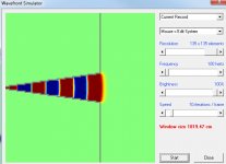
I've simmed a 15Hz horn at 100Hz, with HR, and am not at all surprised to see that the wavefront at the mouth is pretty flat.
The horn shown appears to be flaring too rapidly near the throat to have a 15Hz cutoff. I would expect a 15Hz exponential horn to have a profile more like the one attached. The longer the horn, the greater the curvature of the mouth isophase wavefront.
Attachments
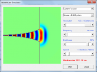
The horn shown appears to be flaring too rapidly near the throat to have a 15Hz cutoff. I would expect a 15Hz exponential horn to have a profile more like the one attached. The longer the horn, the greater the curvature of the mouth isophase wavefront.
Thanks for your interest. You are right (of course).
I could have been more precise and said something like "I've simmed the horizontal component of a 15Hz horn with conical width flare and exponential vertical flare"
My logic: for this scenario, to get a particular horizontal coverage angle, I'd make the side walls straight - or at least straight at the mouth. Most of the curve would be in the top wall. Vertical coverage angle could be any angle, it wouldn't really matter. In this application, you'd have to climb a tree to critique the vertical dispersion.
There's no way to generate such a horn to 'tell' the wavefront sim all this*, so I 'cheated' - I used the autopilot to make a 15Hz horn, then converted it to conical so I had something of roughly the right size (that is: with a cutoff well under 100Hz) to import to the wavefront simulator.
*although I know you can do it in the Export menu form the Schematic window - which is a great feature! I have simmed and built a big midrange horn with info from this feature.
Regardless of size, the acoustical point of origin located at the horn throat of each cell must be located within 1/4 wave length of adjacent cells for the upper pass band to "seamlessly" sum with adjacent cells. The acoustical points of origin must describe the central axis of the arc the cells describe.
I had to read this a couple of times to get it. I have the feeling that I have seen this info before, but it didn't stick because I didn't really understand it.
So that would mean that using a tight array rather than a single-driver multicell (e.g. 5 small horns splayed to give the ~same mouth as a single Altec 511) will always have a relatively limited HF bandwidth, since the acoustic point of origin will always be relatively big?
"the horn throat of each cell must be within 1/4 wave length of adjacent cells" - so that would mean that cloning an existing multicell, but quadrupling the cell number would give + 1 octave of good HF? Without your statement, I would have though the same thing, but that it was mouth size (rather than throat cell distance) that caused it.
That would make for a very fine and fiddly throat... but maybe modern gear (a good 3D printer) makes this more DIY feasible than it used to be.
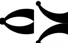
The attached image is meant to represent (use your imagination!) two different horn layouts for a 2-driver and 2-horn system.
If the curvature and all other details were identical, the system on the left would have better HF than the one on the right, because the "point of origin" is smaller*?
Is there an easy way to explain how the air / sound at the mouth would 'know' which way around the throats were, and how big the point of origin was?
*to keep this on topic: to get more bandwidth from a row of bass horns, my left image gives a smaller "point of origin" than the earlier depictions (of parallel and straight horn arrays).
Attachments
The Direct software takes the polar plot of the TEF measured speakers and subs then taking into account the physics behind wave propagation they make plots
Thanks, that clears up a lot of confusion. Is there a link or something to this information?
Quote:
Originally Posted by just a troll:
LOL. You can't let it go, can you? If everyone that disagreed with someone else started namecalling all discussions would be functionally impossible. Your behavior here leaves something to be desired.
Audio choices would be so much easier if you could make them simply by looking at pictures,or graphs, rather than actually listening to the different devices in the myriad configurations that attempt to reproduce, or create sound.
Studying the theory and looking at pictures is a great way to learn. You don't need to hear a deep notch two octaves wide to know that it's a massive design flaw. Sometimes things like that are a necessary evil but definitely not in this case.
I think there's way too much attention being given to wavefront shapes here.
Even if the wavefront was flat as a pancake exiting the horn mouth it would begin to curve immediately as soon as it hit free air. This is made very clear in the Kolbrek paper showing the plane wave exiting a tube.
Sound is round, it will attempt to disperse in all directions as soon as possible so even a planar wave will become curved with distance.
OP's hot tub is 30 feet back from the horn mouth, even if the wavefront was flat exiting the horn (it's not, it's curved) by the time it got to the hot tub it would be significantly curved.
Last edited:
OP's hot tub is 30 feet back from the horn mouth, even if the wavefront was flat exiting the horn (it's not, it's curved) by the time it got to the hot tub it would be significantly curved.
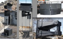
My 15 Hz stereo bass horns will be roughly 14 feet tall, and 32 feet wide (combined). Thus I will be sitting closer to my horns, then my horns are in diameter. I would consider this near-field. My horns are going to produce large & flat (aka gently curved) sound waves into my listening area. The perimeter of each wave will be about 10 inches apart from eachother when they exit the horns - and specifically not 15 feet apart.
FEA lobing simulations will be skewed if you model 450 square feet of horn mouths as point-sources, within the near-field. I am specifically NOT saying that I won't have any lobing in the bottom octaves, but rather that I don't believe they will be as a significant of issue, as your previous simulations have shown.
When my horns are built, we'll take the Pepsi Challenge. I'll bust out the signal generator, and some beer & pizza, and we can walk around to listen for destructive nodes in the sound field 🙂
Last edited:
Art wrote:
Regardless of size, the acoustical point of origin located at the horn throat of each cell must be located within 1/4 wave length of adjacent cells for the upper pass band to "seamlessly" sum with adjacent cells. The acoustical points of origin must describe the central axis of the arc the cells describe.
2) Not necessarily so, if the horns are designed to seamlessly array, they may have nearly as good polar response as a multi-cell- but multi-cell polar response is not that great, the design choice to use multi- cells rather than the better-sounding, better polar response "radial" exponential horns was application driven. The multi-cell horns covered a much greater vertical coverage angle than an exponential radial horn, they have extremely narrow HF dispersion, and because of the narrow vertical dimension, suffer from "pattern flip", a 12" vertical dimension horn would start to "go omni" in the vertical dispersion below 1130 Hz, while the horizontal pattern would remain the same, usually 60 or 90 degrees. Since the HF horn typically covered from 400-500 Hz up, in auditoriums with a wide vertical seating requiring each seat to "sound the same" , several radial horns would need to be arrayed vertically to cover the same vertical angle of a multi-cell.
There actually were plenty of crude throat adaptor "plumbing" devices that could be used either to have one driver drive multiple horns, or when you needed more SPL, but only the coverage pattern of one horn, two or more drivers could be plumbed on to the same throat.
All the "plumbing" comes with a sonic penalty, a single conical horn performs better in almost all aspects, other than one very important aspect in "ye olden days"-efficiency. The HF driver is "painted in to a corner" in terms of excursion, to have decent output level extending in to the top octave above 8kHz, the distance from the diaphragm to the phase plug can not be more than about 1mm. Because the old systems were always at best two- way (Western Electric made a famous driver /horn that was used single way from around 60 Hz to 8kHz) the crossover was best around 500 Hz, the 15" would "beam" if used higher, the HF driver's diaphragm would hammer itself to death if used below.
Next phase was to use a separate "tweeter" horn to relax the midrange excursion limitations of a "full bandwidth" HF driver. Then the blues had a baby, and called that baby rock and roll, and rock and rollers found they could horn load smaller cone drivers and use them for low mid, pushing the mid driver up to 1000 to even as high as 3kHz, the midrange excursion was no longer the limitation, power was. In the early PAs, usually the failure mode was shattered diaphragms, in the rock and roll world, burnt voice coils were the norm.
Continuing the history and evolution of horn systems, the distant positions between pass bands becomes a severe problem if vertical coverage is considered- a four way stack can be made to sound great on axis, but will sound like crap in the balcony. Back in 1991, I developed the Maltese "nested horn" system, a high horn inside a low mid horn inside a 67.5" deep bass horn. The cabinets were pyramid shaped, the front 45" x 45", the back only about 10" x 10". Other companies had nested horns, but had not also designed a rigging system to array their product.
The Maltese system may have been the first "rock and roll" road system that could be rigged in any portion of a sphere, and have the acoustical point of origin located at the horn throat of each cell located within 1/4 wave length of adjacent cells, with the acoustical points of origin describing the central axis of the arc the cells describe.
Functionally it was exactly what Tom Danley later called the Unity horn, in fact, the DSL SH-25 looks remarkably similar to the Maltese HF horn I demonstrated to him years before the Unity design appeared.
Tom, being a much brighter fellow than me, fixed several serious flaws in the Maltese system- the nested horns did not have a uniform polar response throughout the full range, and the "nesting" caused problems with reflections back into the throat. Like a much better implementation of the old "plumbing " that could couple a mid and high driver to the same horn, Tom took that concept to a new level of "rock and roll", having cone woofers, cone midrange and high frequency drivers all share the same horn- a brilliant idea whose time had come due to excursion and power handling of the drivers used in the various pass bands was by then an order of magnitude greater than in the "bad old days".
3) In reality, HF multi-cells have so many things "wrong" that can't be fixed by any level of attention to detail that unless you like the "interesting" sound they impart, there is just no compelling reason to use them, other than those applications where "flea-watt" amps are used, and wide vertical coverage angles are desired without a "pinched throat" diffraction approach.
Before moving to Florida, the last audio project I "completed" was using four Maltese HF horns in a quad array, driven by 3.5" "full range drivers. Though the result is "good sounding" the polar response is not, the array using two or four conical horns with classic "Keele break" secondary horns can not be made to sound the same across the desired pattern. I came into that project thinking I could solve some problems that did not seem at all insurmountable, and are not insurmountable, had I simply started from scratch, rather than attempting to re-use 8 old horns. A classic example of spending more time for a compromised result by trying to save time and recycle unused gear for a specific application they were not designed for originally.
4) I would not suggest either of the layouts proposed for any pass band, but the right hand diagram's two throat sections will cross-feed the horn mouth, instead of a single upper "beam" emanating from the center of a single throat, there will be two distinct upper range L/R "beams" that will point in the general direction of the horn throats.
Cheers,
Art
Regardless of size, the acoustical point of origin located at the horn throat of each cell must be located within 1/4 wave length of adjacent cells for the upper pass band to "seamlessly" sum with adjacent cells. The acoustical points of origin must describe the central axis of the arc the cells describe.
1)I just repeated what all the old "horn guys" knew worked best, so you would have heard it before if you read any of their books or posts.1)I had to read this a couple of times to get it. I have the feeling that I have seen this info before, but it didn't stick because I didn't really understand it.
2)So that would mean that using a tight array rather than a single-driver multicell (e.g. 5 small horns splayed to give the ~same mouth as a single Altec 511) will always have a relatively limited HF bandwidth, since the acoustic point of origin will always be relatively big?
3)"the horn throat of each cell must be within 1/4 wave length of adjacent cells" - so that would mean that cloning an existing multicell, but quadrupling the cell number would give + 1 octave of good HF? Without your statement, I would have though the same thing, but that it was mouth size (rather than throat cell distance) that caused it.
That would make for a very fine and fiddly throat... but maybe modern gear (a good 3D printer) makes this more DIY feasible than it used to be.
4)The attached image is meant to represent (use your imagination!) two different horn layouts for a 2-driver and 2-horn system.
If the curvature and all other details were identical, the system on the left would have better HF than the one on the right, because the "point of origin" is smaller*?
Is there an easy way to explain how the air / sound at the mouth would 'know' which way around the throats were, and how big the point of origin was?
*to keep this on topic: to get more bandwidth from a row of bass horns, my left image gives a smaller "point of origin" than the earlier depictions (of parallel and straight horn arrays).
2) Not necessarily so, if the horns are designed to seamlessly array, they may have nearly as good polar response as a multi-cell- but multi-cell polar response is not that great, the design choice to use multi- cells rather than the better-sounding, better polar response "radial" exponential horns was application driven. The multi-cell horns covered a much greater vertical coverage angle than an exponential radial horn, they have extremely narrow HF dispersion, and because of the narrow vertical dimension, suffer from "pattern flip", a 12" vertical dimension horn would start to "go omni" in the vertical dispersion below 1130 Hz, while the horizontal pattern would remain the same, usually 60 or 90 degrees. Since the HF horn typically covered from 400-500 Hz up, in auditoriums with a wide vertical seating requiring each seat to "sound the same" , several radial horns would need to be arrayed vertically to cover the same vertical angle of a multi-cell.
There actually were plenty of crude throat adaptor "plumbing" devices that could be used either to have one driver drive multiple horns, or when you needed more SPL, but only the coverage pattern of one horn, two or more drivers could be plumbed on to the same throat.
All the "plumbing" comes with a sonic penalty, a single conical horn performs better in almost all aspects, other than one very important aspect in "ye olden days"-efficiency. The HF driver is "painted in to a corner" in terms of excursion, to have decent output level extending in to the top octave above 8kHz, the distance from the diaphragm to the phase plug can not be more than about 1mm. Because the old systems were always at best two- way (Western Electric made a famous driver /horn that was used single way from around 60 Hz to 8kHz) the crossover was best around 500 Hz, the 15" would "beam" if used higher, the HF driver's diaphragm would hammer itself to death if used below.
Next phase was to use a separate "tweeter" horn to relax the midrange excursion limitations of a "full bandwidth" HF driver. Then the blues had a baby, and called that baby rock and roll, and rock and rollers found they could horn load smaller cone drivers and use them for low mid, pushing the mid driver up to 1000 to even as high as 3kHz, the midrange excursion was no longer the limitation, power was. In the early PAs, usually the failure mode was shattered diaphragms, in the rock and roll world, burnt voice coils were the norm.
Continuing the history and evolution of horn systems, the distant positions between pass bands becomes a severe problem if vertical coverage is considered- a four way stack can be made to sound great on axis, but will sound like crap in the balcony. Back in 1991, I developed the Maltese "nested horn" system, a high horn inside a low mid horn inside a 67.5" deep bass horn. The cabinets were pyramid shaped, the front 45" x 45", the back only about 10" x 10". Other companies had nested horns, but had not also designed a rigging system to array their product.
The Maltese system may have been the first "rock and roll" road system that could be rigged in any portion of a sphere, and have the acoustical point of origin located at the horn throat of each cell located within 1/4 wave length of adjacent cells, with the acoustical points of origin describing the central axis of the arc the cells describe.
Functionally it was exactly what Tom Danley later called the Unity horn, in fact, the DSL SH-25 looks remarkably similar to the Maltese HF horn I demonstrated to him years before the Unity design appeared.
Tom, being a much brighter fellow than me, fixed several serious flaws in the Maltese system- the nested horns did not have a uniform polar response throughout the full range, and the "nesting" caused problems with reflections back into the throat. Like a much better implementation of the old "plumbing " that could couple a mid and high driver to the same horn, Tom took that concept to a new level of "rock and roll", having cone woofers, cone midrange and high frequency drivers all share the same horn- a brilliant idea whose time had come due to excursion and power handling of the drivers used in the various pass bands was by then an order of magnitude greater than in the "bad old days".
3) In reality, HF multi-cells have so many things "wrong" that can't be fixed by any level of attention to detail that unless you like the "interesting" sound they impart, there is just no compelling reason to use them, other than those applications where "flea-watt" amps are used, and wide vertical coverage angles are desired without a "pinched throat" diffraction approach.
Before moving to Florida, the last audio project I "completed" was using four Maltese HF horns in a quad array, driven by 3.5" "full range drivers. Though the result is "good sounding" the polar response is not, the array using two or four conical horns with classic "Keele break" secondary horns can not be made to sound the same across the desired pattern. I came into that project thinking I could solve some problems that did not seem at all insurmountable, and are not insurmountable, had I simply started from scratch, rather than attempting to re-use 8 old horns. A classic example of spending more time for a compromised result by trying to save time and recycle unused gear for a specific application they were not designed for originally.
4) I would not suggest either of the layouts proposed for any pass band, but the right hand diagram's two throat sections will cross-feed the horn mouth, instead of a single upper "beam" emanating from the center of a single throat, there will be two distinct upper range L/R "beams" that will point in the general direction of the horn throats.
Cheers,
Art
Attachments
Last edited:
Yes, the wavefront shape. If you can get it to (manipulate it to) look like it has come from x and done y, then that's how it will behave.The attached image is meant to represent (use your imagination!) two different horn layouts for a 2-driver and 2-horn system.
If the curvature and all other details were identical, the system on the left would have better HF than the one on the right, because the "point of origin" is smaller*?
Is there an easy way to explain how the air / sound at the mouth would 'know' which way around the throats were, and how big the point of origin was?
Last edited:
The perimeter of each wave will be about 10 inches apart from eachother when they exit the horns - and specifically not 15 feet apart.
It's always center to center distance that is important. The fact that they are 10 inches apart at the edge is not of much relevance.
As soon as the wavefront exits the mouth the wavefront will expand in all directions. That means that at the edges the beam will be crossing and interfering with the beam beside it almost immediately (at least at low frequencies where it's not beaming hard), likely within about a foot of the mouth.
As the wavefront continues it's journey toward the hot tub it will continue to get more and more curved.
FEA lobing simulations will be skewed if you model 450 square feet of horn mouths as point-sources, within the near-field.
Radulescu specifically said Direct is NOT modeling any horn as a point source. He said it uses the actual polar measurements of the speaker and uses the actual physics of wave propagation to simulate the results.
Also, the Danley horns are much closer to a "flat" wavefront than your exponential horn because they are pretty close to conical. So your argument that your wavefront is too gently curved for my software goes out the window.
The Danley Direct software agrees fairly well with the other software I was using too, which does model the sound sources as point source. So clearly the difference isn't that much between the point source round wavefront and the conical horn "flat" wavefront.
And I'm not going to use the other software for anything in this discussion anymore, only Direct. So stop talking about point source sims.
It's not the end of the world, as I showed before it's not nearly as bad as a 60 foot spacing.
Doesn't really matter that much though, as long as you cross over no higher than 80 hz most of your defined audience area is between the yellow notch valleys. And if you can get the horns to beam tighter than 80 degrees or so at 80 hz you might be lucky enough to have very minimal overlap and therefore less extreme notches.
It's not how I would do it but with a steep 80 hz crossover it should be ok, at least in the small audience area you defined earlier.
Shown at 40, 80 and 160 hz.
An externally hosted image should be here but it was not working when we last tested it.
Last edited:
I wonder whether the 'bad polars' of many multicells are not inherent, but due to their vintage & applications (mono, large audiences).2) Not necessarily so, if the horns are designed to seamlessly array, they may have nearly as good polar response as a multi-cell- but multi-cell polar response is not that great, the design choice to use multi- cells rather than the better-sounding, better polar response "radial" exponential horns was application driven.
Some multicells, such as the (2x5 cell) EV horn in Keele's paper had wildly varying beamwidth. They also seem to have too much horizontal pattern for hifi use
...but the polars of the 511 look much better - http://www.audioheritage.org/vbulletin/attachment.php?attachmentid=21535&stc=1&d=1166849612, so maybe adding cells to a good modern hifi horn would be better again?
Quoting Bill Fitzmaurice here:
Logically a multicell is generally going to have a better HF response than a horn of identical shape that's not subdivided, as the smaller cross sections raise the frequency of phase anomalies. What would be interesting to see is a radial CD horn that's been given the multicell treatment and then A/B compared to see the result. I'd imagine the main reason they aren't done that way is the additional cost to manufacture.
That bolded bit seems too low, compared to the attached info. But it seems like stacking radials, or some sort of MTM using them, could be worth considering.The multi-cell horns covered a much greater vertical coverage angle than an exponential radial horn, they have extremely narrow HF dispersion, and because of the narrow vertical dimension, suffer from "pattern flip", a 12" vertical dimension horn would start to "go omni" in the vertical dispersion below 1130 Hz, while the horizontal pattern would remain the same, usually 60 or 90 degrees. Since the HF horn typically covered from 400-500 Hz up, in auditoriums with a wide vertical seating requiring each seat to "sound the same" , several radial horns would need to be arrayed vertically to cover the same vertical angle of a multi-cell.
Bad news. That's not unlike what I was considering - something like that quad + a central (delayed) tweeter. Do you have plots - where did it start to go blah?Before moving to Florida, the last audio project I "completed" was using four Maltese HF horns in a quad array, driven by 3.5" "full range drivers. Though the result is "good sounding" the polar response is not, the array using two or four conical horns with classic "Keele break" secondary horns can not be made to sound the same across the desired pattern. I came into that project thinking I could solve some problems that did not seem at all insurmountable, and are not insurmountable, had I simply started from scratch, rather than attempting to re-use 8 old horns. A classic example of spending more time for a compromised result by trying to save time and recycle unused gear for a specific application they were not designed for originally.
Thanks. That was just a thought experiment to check that I had got the concept.4) I would not suggest either of the layouts proposed for any pass band
Attachments
In one sentence you acknowledged that the makers of Direct 'see' their 45" wide horn as not radiating from a point.It's always center to center distance that is important.
[...]
Radulescu specifically said Direct is NOT modeling any horn as a point source. He said it uses the actual polar measurements of the speaker and uses the actual physics of wave propagation to simulate the results.
In another, you refer to a 32' wide horn as if it had 2 clear centers, and model it thus.
Does that seem 100% consistent?
If the OP builds an ~axisymmetric horn. Plenty of horns use conical flare in the horizontal dimension and put all the curve in the vertical dimension.Also, the Danley horns are much closer to a "flat" wavefront than your exponential horn because they are pretty close to conical. So your argument that your wavefront is too gently curved for my software goes out the window.
You should try reading some of this stuff out loud 🙂So stop talking about point source sims.
Huzzah!It's not how I would do it but with a steep 80 hz crossover it should be ok, at least in the small audience area you defined earlier.
Also: the OP might one day say to himself: "That dear old JAG chappy was right all along, these nulls are driving me utterly bonkers". He could then fiddle with the crossover points, to use just one of the bass horns up to 80Hz, and cut the other(s) an octave lower. That would give him pretty much what you have been suggesting. More subunits = more flexibility.
Most of the excursion is in the last octave, so the lower passed drivers wouldn't be 'wasted'.
- Home
- Loudspeakers
- Subwoofers
- Concrete Bass Horn Design Question