Just replacing resistors semi-randomly with high end parts seems like a poor idea to me.
My reasoning:
1) Without starting with the recommended baseline parts that Nelson designed the amp with, how do you know if you have an improvement or not? Nelson voiced the amp with Dale/Vishay resistors. I wouldn't take his voicing lightly.
2) High end resistors may sound slightly different (although plenty of people will take the other side of that argument) but they may not be an improvement. Peter Daniel has a good ear and I've watched his parts tweaking over the years. Here is what he concludes:
That is not correct. On many occasions I noticed actually degradation comparing to regular resistors. Exotic resistors, or other parts, should be used carefully and chosen specifically for a particular location in a circuit. Not everything works well, and quite often, it is not an improvement but only a different flavour of questionable merit. Please see below my Ono boards: p2p with silver wire, packed with exotic resistors (even trimpots are Vishays) and yet, I didn't really like the results much.
If you want the flexibility to try different resistors later, one idea is that you build 18g solid core wire standoffs on the board in key spots. That way you can solder the resistors to the standoffs and not have to deal with rework and possible screwed up pads. You can start with the baseline and move slowly, part by part, with lots of listening.
I have no plans to swap resistors from Dale/Vishay, but I've added standoffs on the F4 build I just completed so I can swap input and output signal wire later if I want. Neotech 18g solid core copper is good for this.
All that said, I built a PSU with Mundorf caps for my VFET. No idea if that will be an improvement or not. But the power supply is easily swappable without unsoldering if I want to try something else later.
Last edited:
Nicely put Cappy.
I like your system. You can check mine out, we have similar tastes 😉
Best,
Anand.
I like your system. You can check mine out, we have similar tastes 😉
Best,
Anand.
Well, everybody has his/her own choices in DIY I guess.
It is like sitting together in a restaurant at lunch time. Everybody wants lunch and the guy on the next table orders his steak medium while you prefer a burger well-done. So, would you ask the guy to eat a burger because you prefer it ? I guess I did not want to initiate a discussion burger vs. steak, or get educated by the burger eaters to join their taste. So back to the subject:
I have build a lot of dacs, poweramp, solid state, tube etc with many different resistor or cap or diode types, finally I prefer the tx2575 in the signal path, it simply is transparent like hell, nothing is coloured etc. But someone else might be perfectly happy with his cmf or carbon, which is fine for me as well. I did use the polyprops of Mundorf in many different applications and they never really suck, actually they are very good, in the last years for coupling caps I prefer Duelund Cast though. In my tube amp no lytics, only polyprop as well int the PSU. But in my F5 and Vfet Mundorf lytics and chokes from Ae Europe.
I guess there is no doubt that those resistor which are directly in the signal path will make a bigger difference than those who are in the support circuit, but maybe I am wrong.
My question was simply: Which parts may have a bigger impact (besides the transistors themselves), even if your personal choice might be cmf (I will for sure not argue on your taste or choice)
My question was simply: Which parts may have a bigger impact (besides the transistors themselves)...
My guestimate would be currently:
- R1, R3
- R2, R23, R24
- R25, R26
- R4
R31/10K ?
and R21 and R22 ?
Other front-end R's ?
Please help find us the correct answer to Blitz question
Have fun

Attachments
If you want the flexibility to try different resistors later, one idea is that you build 18g solid core wire standoffs on the board in key spots. That way you can solder the resistors to the standoffs and not have to deal with rework and possible screwed up pads. You can start with the baseline and move slowly, part by part, with lots of listening.
Thanks Cappy for the tips 🙂
Anand - Nice system back at ya. 😉
Soundhappy - You are welcome. But, I just checked and 18g solid core won't fit in the resistor holes for the VFET PCBs. They are smaller holes than on the F4 boards. The 18g does fit in the input/output pads. I'm guessing 20 gauge will fit.
Also, don't go too crazy with the number of standoffs or height. Otherwise you may be incorporating Easy Listening 105 FM (ou RTL2 Le Son Pop-Rock) into your soundscapes!
R31/10K ?
and R21 and R22 ?
Other front-end R's ?
Please help find us the correct answer to Blitz question
Have fun
This is a very controversial subject, but here are my 2 cents: The following Bruce Hofer presentation talks about low THD design for audio and is frequently referenced, page 18 summarises his resistor recommendations: Recommendations for Audio Circuits ... Personally I would consider R3, R4, and R31 as candidates for lower TC resistors and so I decided to get Vishay PTF 56 and PTF 65 with 5 ppm Tempco for those. I am not so sure if it really makes any noticeable difference but at the very least you may sleep better.
Not wanting to be "that guy", but maybe you guys should just build the amp first before thinking about how to improve it. I mean, the patience this guy must have, conceiving a modern way to use some vintage parts, with a poop-ton of relationships occurring within the circuit itself... and then adapt it for diy. And people are already fussing over the quality of a part. Listen, if you *really knew* that it made that much of a difference, you'd just do it. You wouldn't have to talk about it. You wouldn't come here seeking some validation or assurance. You would just identify the part, you would go and order the *right* part, and then you'd enjoy the amp from here to eternity.
This is the kind of answer which is not even try to be an answer to my question. I will for sure build it with tx2575 and other high quality part. But at 12$ a piece you want to be selctive. If you have a simple tube amp or a purist version of a F5 a la Petwr Daniel it is not very difficult to just do it, not too mam parts in the amp left...but here we have a bit more. But as there seems not too many how know or care, I will just go ahead with my limited understand and order now as written above...
This is the kind of answer which is not even try to be an answer to my question. I will for sure build it with tx2575 and other high quality part. But at 12$ a piece you want to be selctive. If you have a simple tube amp or a purist version of a F5 a la Petwr Daniel it is not very difficult to just do it, not too mam parts in the amp left...but here we have a bit more. But as there seems not too many how know or care, I will just go ahead with my limited understand and order now as written above...
Seems to me that P3 and P4 are in the signal path and should also be included in your list.
nash
Resistors make a difference. Don't let anyone tell you they don't. There is an odd thing that happens with the objectivist/subjectivist debate; that is that objectivists will argue that such things (including capacitors) can't or won't make a difference despite the fact that the difference between the parts is measurable. They do this with other things like power cords (which are also measurable and with fairly simple test equipment). The fact is most of them don't bother to do the measurements despite claiming to be objective.
Any resistor in series with the signal should be scrutinized. Lower values tend to less audible than higher values. Resistors in emitter circuits can have an effect as well. Resistors have a spec wherein the total resistance can vary with the voltage drop across the part. This can affect the bias of the transistor (or tube). This affects performance.
Generally if you want to know how a resistor sounds the entire circuit should be treated with that style resistor. I find that most of the Vishays have a bright quality; some of the naked ones are pretty good. Mills makes some nice parts too but the non-inductive parts can be a bit large and may introduce hum pickup. I prefer Caddock; they make a particular model that is non-inductive even at radar frequencies, however its a bit spendy and Caddock will only make them for us on an order basis- they don't stock them.
Michael Percy stocks some of the more exotic resistors. You might contact him if you are looking to try some out.
I know this topic is controversial, but all I can tell you about that is there's something a little odd about objecting to a part that measures better (has better specs) and then saying that the cheap part will sound just as good. There's no proof!! That cannot possibly be described as an objective position and for that matter is not subjective either! IOW its nonsense.
One of the problems here is the kind of change that results will be a small reduction in distortion. This is most likely going to be higher ordered harmonics and in trace amounts. The issue here is that the human ear/brain system converts distortion into tonality (for example, many tube circuits sound 'warm' due to a 2nd harmonic). The higher orders are used by the ear/brain system to gauge sound pressure. So if they are messed with even in tiny trace amounts that are hard to measure, it can be audible as brightness and harshness.
Understanding how the ear/brain system works is the most important thing to know in audio- after that, its understanding how to engineer something so that it takes advantage of the various perceptual rules employed.
I agree completely with you...I ordered my first exotic resistor like Mills and Caddock 20years ago from Michael Percy. It is for me as well a stupid discussion whether a resistor makes a difference in SQ or not, It does. But what is really beconig annoying is the missionary qualities some people start to show, that they want to force other to follow their believes.
Some of them remind me to those who argued that the planet is a flat thing instead of a globe...but arent we now 500 years further down the road ? Still the same qualities in behavior...impressive.
Some of them remind me to those who argued that the planet is a flat thing instead of a globe...but arent we now 500 years further down the road ? Still the same qualities in behavior...impressive.
Ed Simon wrote an excellent article about resistors non-linearity for linearaudio.net (volume 1, the article can be bought for €0.99).
Does it matter whether a resistor is magnetic or not? Proof preferred over subjective opinions... 😉
That's my only concern before ordering parts for my VFET amp. 😀
Does it matter whether a resistor is magnetic or not? Proof preferred over subjective opinions... 😉
That's my only concern before ordering parts for my VFET amp. 😀
An excerpt from the (soon to be completed) build guide -
(The "how it works" for the front end is still unedited)
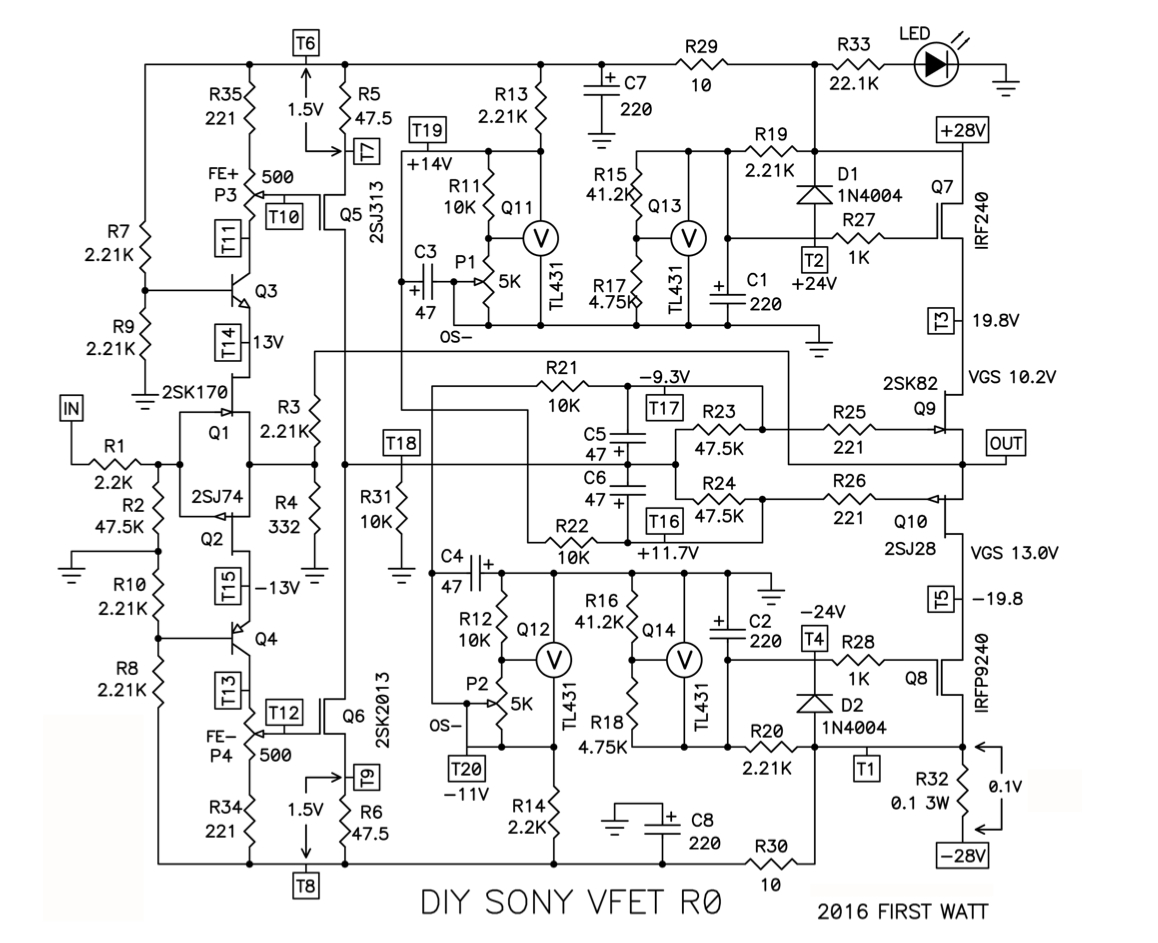
Please refer to the above schematic for component names
The output stage -
The Vfets themselves are wired as a complementary pair in source-follower mode. These add current gain to the signal sent to their Gate pins (to be able to drive speakers with a low output impedance) but have no voltage gain.
That’s it - the voltage gain has happened in the Front-End, and the Vfets just add current capability. 🙂 But it’s not quite that simple… is it?
Well, it actually is, until you realize that the DC powering up the Vfets must be regulated for a stable DC voltage and low noise, the same with the bias voltage. Also, both the rail voltage and the bias voltage have to power-up and power-down in a specific order to keep the Vfets from trying to draw a ton of current when the circuit is powered up.
What’s the proof of Nelson’s genius in this circuit? In how simple (and quite effective) the regulator sections have been designed. Let’s talk about that now.
Regulators
Each rail of each channel has 2 regulators, for a total of 4. Each of the two rails has a bias regulator and an output stage regulator. For clarity’s sake, I’m now going to talk about the positive rail’s regs - the negative rails have the same thing, just in a mirror image.
Both regulators use a TL431, a nice little 3-pin shunt reg that can have it’s output voltage set by 2 resistors. Looking at the schematic around Q11, you can see the unregulated voltage coming from the rail through a simple RC filter (R29 and C7) then through R13 (2.21K) and then the set resistors R11 (10K) and P1 (5K pot).
Because one of the two set resistors is a potentiometer wired as a variable resistor, changing that pot value changes the set voltage which provides Vfet voltage bias. It is very important that the bias voltage is place when power is applied to the Drain of the VFET, so this regulator circuit (bias reg) is designed to charge up much faster than the regulated voltage powering the Drain. (The output stage regulator)
Remember how it was mentioned earlier that the Sony Vfets are “Depletion” mode? They are normally on, letting current flow, and require a negative voltage applied to the gate to turn them off (this for the N type – The P channel devices require a positive voltage), or to otherwise set the value of the current (bias) through the VFET.
Looking at the regulated voltage at T19, (+14V) you want to note that it crosses over and connects to the gate of the negative P-channel Vfet Q10. The positive N-channel Vfet Q9, is likewise biased from the opposite rail. This is the opposite of what you are normally going to see with complementary Mosfet followers.
Moving on to the output regulators, you can see the circuitry near Q13 looks similar to the other reg, the exception being the voltage setting resistors are both fixed resistors. (R15, R17) These resistors and the TL431 make a voltage of 24V, seen at T2. This fixed voltage is controls the gate of a power Mosfet, Q7. This Mosfet is slaved to the regulator and lets the tiny TO-92 package regulator control many amps of current. Wonderful! This is necessary because the regulator needs to regulate the power going to the output stage which drives your speakers.
However there is no free lunch, and the Mosfet eats up about 4.2V (the Mosfet’s Vgs) in payment for doing it’s job. This is why you see a regulated rail voltage presented to the drains of the*Vfets of 19.8V (or so). An important part of the rail regulators is C1 (220uF), there to delay the arrival of this 19.8V to give the bias regulator time to ramp up. More about this here;
Power-up and power-down sequencing.
Back to depletion mode devices - The Vfets are normally on, right? We need to apply a bias voltage to control them. If the bias voltage isn’t there controlling current flow when the rail regulators power up, the Vfets will conduct an excessive amount of current and the 40-year old, completely irreplaceable smoke made from vintage Japanese un-obtainium, ground unicorn horn and pixie dust will escape. A sad result which will also smell bad.
So we must have the bias regulator working before the rail voltage is turned on. How did Nelson do it? A simple application of the time constant to charge 2 differently sized capacitors in the regulator circuits. The regulator with the smaller capacitor will turn on before the one with the larger cap. These caps in the race are C3 (47uF) on the bias reg and C1 (220uF) on the output regulator. It’s a 4.7-to-1 ratio and C3 will be charged about 4.7 times sooner.
The TL431 are shunt regulators, so they do not conduct current until the voltage rises to the regulation value, and then they conduct so as to hold that value.
So what about power down? The rail voltage needs to be turned off before the bias voltage. (the opposite of power-up) BUT, the big cap/small cap ratio will NOT work in our favor when shutting down. It would work exactly how you’d expect, where the small cap will discharge before the big one.
So what? The VFETs will drain the supply quickly enough, but when the supply voltage drops down quickly we may find the Gate to Source voltage (Vgs) of the Mosfet at a high enough voltage to stress the transistor into failure. It's not that likely, but everyone knows that Pass wears both a belt and suspenders to hold up his pants, and this is reflected in his design.
The fix is a simple 2-cent diode. On power down, D1 will be a very attractive and very low-resistance discharge path for C1, discharging it rapidly and turning Q7 (and Q13) off, and therefore the rail voltage to the Vfets. Because there is no special path for C3 in the bias regulator to discharge, it will operate for a longer time, which is perfectly ok.
The stuff in the middle.
Ok, so far everything has been explained except for the wiggles in the center of the schematic near T16 and T17. Remember how the bias voltage regulator is set by the divider made from R11 and P1? This is a DC value but we also need to let the AC have it’s say in the circuit, as the AC is our music. 🙂 The Front-End output signal was all big and powerful the last time we left it at T18. Now this signal needs to get to the Gates of the Vfets to move our speakers, and that signal (even though it’s AC) can get pretty darn big. Big enough that it’s voltage could effect the current flowing through the regulator set resistors. The network of C5, C6 and R21 through R24 prevent the music signal from having much influence on the bias regulators. Stable bias makes for happy Vfets, so this is a good thing.
What’s left… Um… R25 R26 (221ohm) are gatestoppers for the Vfet, R33 (22.1K) adjusts the brightness of the LED (which must be blue, this is a Pass amp, after all…) and R32 (0.1ohm) gives a place to measure the output stage current. (Bias)
Global feedback is applied from the output stage from the Vfets to the Jfets through R3 (2.21K), and then R4 (332ohm) to ground.
(The "how it works" for the front end is still unedited)
Please refer to the above schematic for component names
The output stage -
The Vfets themselves are wired as a complementary pair in source-follower mode. These add current gain to the signal sent to their Gate pins (to be able to drive speakers with a low output impedance) but have no voltage gain.
That’s it - the voltage gain has happened in the Front-End, and the Vfets just add current capability. 🙂 But it’s not quite that simple… is it?
Well, it actually is, until you realize that the DC powering up the Vfets must be regulated for a stable DC voltage and low noise, the same with the bias voltage. Also, both the rail voltage and the bias voltage have to power-up and power-down in a specific order to keep the Vfets from trying to draw a ton of current when the circuit is powered up.
What’s the proof of Nelson’s genius in this circuit? In how simple (and quite effective) the regulator sections have been designed. Let’s talk about that now.
Regulators
Each rail of each channel has 2 regulators, for a total of 4. Each of the two rails has a bias regulator and an output stage regulator. For clarity’s sake, I’m now going to talk about the positive rail’s regs - the negative rails have the same thing, just in a mirror image.
Both regulators use a TL431, a nice little 3-pin shunt reg that can have it’s output voltage set by 2 resistors. Looking at the schematic around Q11, you can see the unregulated voltage coming from the rail through a simple RC filter (R29 and C7) then through R13 (2.21K) and then the set resistors R11 (10K) and P1 (5K pot).
Because one of the two set resistors is a potentiometer wired as a variable resistor, changing that pot value changes the set voltage which provides Vfet voltage bias. It is very important that the bias voltage is place when power is applied to the Drain of the VFET, so this regulator circuit (bias reg) is designed to charge up much faster than the regulated voltage powering the Drain. (The output stage regulator)
Remember how it was mentioned earlier that the Sony Vfets are “Depletion” mode? They are normally on, letting current flow, and require a negative voltage applied to the gate to turn them off (this for the N type – The P channel devices require a positive voltage), or to otherwise set the value of the current (bias) through the VFET.
Looking at the regulated voltage at T19, (+14V) you want to note that it crosses over and connects to the gate of the negative P-channel Vfet Q10. The positive N-channel Vfet Q9, is likewise biased from the opposite rail. This is the opposite of what you are normally going to see with complementary Mosfet followers.
Moving on to the output regulators, you can see the circuitry near Q13 looks similar to the other reg, the exception being the voltage setting resistors are both fixed resistors. (R15, R17) These resistors and the TL431 make a voltage of 24V, seen at T2. This fixed voltage is controls the gate of a power Mosfet, Q7. This Mosfet is slaved to the regulator and lets the tiny TO-92 package regulator control many amps of current. Wonderful! This is necessary because the regulator needs to regulate the power going to the output stage which drives your speakers.
However there is no free lunch, and the Mosfet eats up about 4.2V (the Mosfet’s Vgs) in payment for doing it’s job. This is why you see a regulated rail voltage presented to the drains of the*Vfets of 19.8V (or so). An important part of the rail regulators is C1 (220uF), there to delay the arrival of this 19.8V to give the bias regulator time to ramp up. More about this here;
Power-up and power-down sequencing.
Back to depletion mode devices - The Vfets are normally on, right? We need to apply a bias voltage to control them. If the bias voltage isn’t there controlling current flow when the rail regulators power up, the Vfets will conduct an excessive amount of current and the 40-year old, completely irreplaceable smoke made from vintage Japanese un-obtainium, ground unicorn horn and pixie dust will escape. A sad result which will also smell bad.
So we must have the bias regulator working before the rail voltage is turned on. How did Nelson do it? A simple application of the time constant to charge 2 differently sized capacitors in the regulator circuits. The regulator with the smaller capacitor will turn on before the one with the larger cap. These caps in the race are C3 (47uF) on the bias reg and C1 (220uF) on the output regulator. It’s a 4.7-to-1 ratio and C3 will be charged about 4.7 times sooner.
The TL431 are shunt regulators, so they do not conduct current until the voltage rises to the regulation value, and then they conduct so as to hold that value.
So what about power down? The rail voltage needs to be turned off before the bias voltage. (the opposite of power-up) BUT, the big cap/small cap ratio will NOT work in our favor when shutting down. It would work exactly how you’d expect, where the small cap will discharge before the big one.
So what? The VFETs will drain the supply quickly enough, but when the supply voltage drops down quickly we may find the Gate to Source voltage (Vgs) of the Mosfet at a high enough voltage to stress the transistor into failure. It's not that likely, but everyone knows that Pass wears both a belt and suspenders to hold up his pants, and this is reflected in his design.
The fix is a simple 2-cent diode. On power down, D1 will be a very attractive and very low-resistance discharge path for C1, discharging it rapidly and turning Q7 (and Q13) off, and therefore the rail voltage to the Vfets. Because there is no special path for C3 in the bias regulator to discharge, it will operate for a longer time, which is perfectly ok.
The stuff in the middle.
Ok, so far everything has been explained except for the wiggles in the center of the schematic near T16 and T17. Remember how the bias voltage regulator is set by the divider made from R11 and P1? This is a DC value but we also need to let the AC have it’s say in the circuit, as the AC is our music. 🙂 The Front-End output signal was all big and powerful the last time we left it at T18. Now this signal needs to get to the Gates of the Vfets to move our speakers, and that signal (even though it’s AC) can get pretty darn big. Big enough that it’s voltage could effect the current flowing through the regulator set resistors. The network of C5, C6 and R21 through R24 prevent the music signal from having much influence on the bias regulators. Stable bias makes for happy Vfets, so this is a good thing.
What’s left… Um… R25 R26 (221ohm) are gatestoppers for the Vfet, R33 (22.1K) adjusts the brightness of the LED (which must be blue, this is a Pass amp, after all…) and R32 (0.1ohm) gives a place to measure the output stage current. (Bias)
Global feedback is applied from the output stage from the Vfets to the Jfets through R3 (2.21K), and then R4 (332ohm) to ground.

The question came up about how soon this is happening.
I have tested 300 pair of devices for the last round, which still leaves some
for repairs.
They will ship to diyAudio this month, but it will still take some time for the
rest of the parts, particularly the brackets and pc boards to be in place.
I have tested 300 pair of devices for the last round, which still leaves some
for repairs.
They will ship to diyAudio this month, but it will still take some time for the
rest of the parts, particularly the brackets and pc boards to be in place.
An excerpt from the (soon to be completed) build guide -
....Remember how the bias voltage regulator is set by the divider made from R11 and P1? This is a DC value but we also need to let the AC have it’s say in the circuit, as the AC is our music. 🙂 The Front-End output signal was all big and powerful the last time we left it at T18. Now this signal needs to get to the Gates of the Vfets to move our speakers, and that signal (even though it’s AC) can get pretty darn big. Big enough that it’s voltage could effect the current flowing through the regulator set resistors. The network of C5, C6 and R21 through R24 prevent the music signal from having much influence on the bias regulators. Stable bias makes for happy Vfets, so this is a good thing.
What’s left… Um… R25 R26 (221ohm) are gatestoppers for the Vfet, R33 (22.1K) adjusts the brightness of the LED (which must be blue, this is a Pass amp, after all…) and R32 (0.1ohm) gives a place to measure the output stage current. (Bias)
Global feedback is applied from the output stage from the Vfets to the Jfets through R3 (2.21K), and then R4 (332ohm) to ground.
Fantastic work 6L6 thanks for guide teaser. Looks promissing.
On your photo with schematic in the left corner i see add informations about damping factor, THD , gains etc.
Guess is from "VIP
 edition" ?
Cheers
Attachments
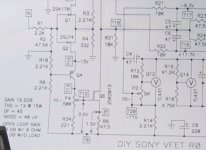
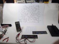
On your photo with schematic in the left corner i see add informations about damping factor, THD , gains etc.
Interesting, I didn't notice that the schematic was different. I printed my bench copy from the first draft of Nelson's article on Firstwatt.com . For whatever reason draft 2 doesn't have the info in the corner.
http://www.firstwatt.com/pdf/art_diy_sony_vfet_1st_draft.pdf (Still labeled 1st draft... lol 🙂 )
- Home
- Amplifiers
- Pass Labs
- Sony vFET Amplifier Part 2