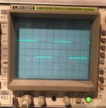
Nice squarewave. No overshoot, no ringing, no glitches in the rising, nor falling edges.Made a few mods to the amps. Standardised on the simple VAS as per the AKSA design. Reduced the idle current through the VAS and the drivers to reduce the temperature of the devices to very warm instead of quite darn hot. Tuned up the bias and dc-offset whilst about it.
The forum seems to like turning my photos sideways without asking me - maybe the mods can fix it.
Member
Joined 2009
Paid Member
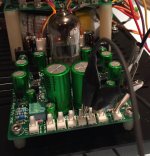
It is nice to have a compact unit, but I find I often end up picking a chassis that's really too small for the project and it becomes a fight to get it all in!very nice case and very compact build. Congrats!
The purpose of this project is to have an amp I can use as a reference to the sound and behaviour of the AKSA amp. The two-device VAS was an experiment I couldn't resist when I did the pcb layout but the original purpose was always to build the AKSA. We both know there are many ways to improve the technical performance of the AKSA amp, but it changes the sound. I rather like the sound of the AKSA amplifier. If I want super clean & smooth I grab my TGM8. Maybe I'll want something in between these two approaches one day - would your Quasi fit into that description I wonder ?What made you settle on the simple VAS?
Thanks Andrew, yes, the square wave looks OK. I think I should add some capacitance to the output and see how well it behaves but I wasn't brave enough - driving a square wave into a capacitor is one way to blow up the output stage and I don't have any more matched pairs!Nice squarewave. No overshoot, no ringing, no glitches in the rising, nor falling edges.
Member
Joined 2009
Paid Member
Quick listening test this evening - the sound is now much improved and much to my liking.
I was able to remove the 'dirty buz' by correcting a mis-wiring of the shielded input signal cable (shield to chassis instead of signal gnd - ugh!). I think running the drivers and VAS at a cooler temperature was also key in this transformation of the sound to where I thought it should be at.
Main limitation is increasing distortion at high volumes - which is likely a combination of the limitations of the amplifier and the speaker - I'm using a 4" full range MLTL which has it's limits.
Member
Joined 2009
Paid Member
coaxial screen is a signal wire.
I think the confusion comes from the fact that a screened 2core is fundamentally different from a screened 1core
Screened 1core is coaxial. The screen is the Signal Return and must be wired close coupled with the Signal Flow all the way from Source to Receiver.
Screened 2core has the Signal Flow and Signal Return on the two cores. These must remain close coupled all the way from Source to Receiver. The screen is required to "shield" the signals when the 2cores are exposed to interference. In this case the screen goes to chassis and becomes an extension of the enclosure.
I am surprised you have not tested the amplifier with a range of capacitances both after the output inductor and before the output inductor.
Last edited:
Member
Joined 2009
Paid Member
Well I initially treated it as a screened 2 core, the cores used for signal and signal return as you say and the shield to the chasis. But of course, this cable is inside the chasis so the thinking was wrong on my part. And even without anything plugged into to the RCA connectors the result was ugly. Perhaps it was also a consequence of where I located my protective earth in terms of dirty currents. Anyhow, it's quiet now that the screen is connected to the signal return.
I'm too lazy with regards the capacitance test. I do at least have some good excuses - firstly it's a proven design, secondly there are no plans to use it with unusual loads.
I'm too lazy with regards the capacitance test. I do at least have some good excuses - firstly it's a proven design, secondly there are no plans to use it with unusual loads.
My suggestion is that you correct the shield to only one end of signal return and not at both ends.
Gareth,
the smile on your avatar is well deserved. Well done and thank you for taking us on the trip.
the smile on your avatar is well deserved. Well done and thank you for taking us on the trip.
Member
Joined 2009
Paid Member
Yup - that's exactly what I did.My suggestion is that you correct the shield to only one end of signal return and not at both ends.
Gareth,
the smile on your avatar is well deserved. Well done and thank you for taking us on the trip.
Thanks for the good words - but I think it may be a crazed man smiling at you 😀
Member
Joined 2009
Paid Member
Triode Buffer
A quick play with the buffer circuit this evening.
I found that the triode was drawing about 6mA and I wanted to see closer to 8mA, so I changed out a pair of resistors to get the operating point up to 8mA. This also relieves a bit of the heat stress on the shunt regulator devices.
I gave the buffer a 1kHz sq. wave test signal from the o'scope front panel. It produced a nice clean sq. wave at the output. The gain was roughly 0.92. that's all the bench work I can fit in this week - may get back on it this weekend.
Attachments
Gareth,
the smile on your avatar is well deserved. Well done and thank you for taking us on the trip.
Ditto, Gareth, though I find that nostalgia is not what it used to be.....
Hugh
Member
Joined 2009
Paid Member
ha!
... well I had a chance to put the triode buffer before the power amp and verify that it sounds just fine. It's rather transparent on first listening.
Tried hooking up the phono amp but I get a lot of hum, likely wiring, hopefully not intractable given the small chassis.
... well I had a chance to put the triode buffer before the power amp and verify that it sounds just fine. It's rather transparent on first listening.
Tried hooking up the phono amp but I get a lot of hum, likely wiring, hopefully not intractable given the small chassis.
Try using a variable mu, frame grid tube as buffer. It has a different harmonic profile than a conventional triode and the sound is richer in low orders, particularly H2/H3/H4.
HD
HD
Member
Joined 2009
Paid Member
I may have to deal with a different problem first - I seem to have forgotten an output capacitor for the phono amp, which means I have 2V of dc-offset at the output. I could include a cap into the connecting wires easy enough, but it's starting to feel like the perfectionist in me would rather re-spin the pre-amp board and fix up a few things.
The distortion profile could be changed with the variable mu tube like the GK1 but I can probably get similar by adjusting the bootstrapped load - at least in simulations it looks simple enough. If I re-spin the board I could add a trim-pot. Blast, I'm quite tempted but it would be a bit of a delay in the project to re-spin the board and I wanted it done next week.
The distortion profile could be changed with the variable mu tube like the GK1 but I can probably get similar by adjusting the bootstrapped load - at least in simulations it looks simple enough. If I re-spin the board I could add a trim-pot. Blast, I'm quite tempted but it would be a bit of a delay in the project to re-spin the board and I wanted it done next week.
Member
Joined 2009
Paid Member
Well, another solution is to move the volume pot to after the triode buffer. Then the phono can feed directly into the triode buffer which has a dc blocking cap at the input.
This seems to work. Initial listening on my turntable says it is still too noisy, too much hum but I am hopeful that this can be improved on still with better attention to the wiring. The sound isn't balanced to my ears though (Nora Jones LP) with too much brightness in the treble. It may not be an issue with the phono amp per-se as I've got exactly the same issue playing this turntable into my Marantz integrated amp too. Needs further investigation - perhaps the tracking weight needs to be increased.
I took the phono amp out of the loop and fed my iphone into the buffer - then volume pot - then power amp. The sound is very good, quite encouraging.
Last edited:
Moving your pot would change the available headroom from being infinite. You are now limited to that of the front end.
Last edited:
Member
Joined 2009
Paid Member

A very perceptive question.
The amplifier has a maximum input of +/-2V before clipping. The triode buffer has more than 2V of headroom. The headroom limit is the -ve rail (less the Vce(sat) of the BD140 which is tiny), the available +ve swing is very large and inconsequential. And the buffer clips gracefully at the -ve rail of course. I haven't tried feeding it with a signal large enough to clip yet so I may try that out.
But distortion is another question. More headroom to the negative rail is probably a good idea for keeping distortion low. But with the buffer before the volume control the distortion is going to be independent of the volume setting and also a lot higher. This might explain why it was sounding so sweet. This is not the case with the buffer after the volume control where the signal will often be small and distortion very low. Furthermore, it will be cleanest at low volume and increasingly coloured at higher volumes; as a user of the amp I do see some advantages in having a volume independent distortion profile from the tube buffer.
Further thoughts on this one ?
Last edited:
Member
Joined 2009
Paid Member
I do see some advantages in having a volume independent distortion profile
This has been a bit of a revelation for me, it may dictate my approach to future amplifier (incl. hybrid) designs.
Member
Joined 2009
Paid Member
Well I did a lot more poking about today to understand the noise performance of this circuit. I'm quite happy with the power supply and power amps, it's all down to the pre-amp now.
I've noticed that the particular tube I'm using (6N23P) has a fair bit of noise, or tube 'rush' as some folk call it, when the volume is on maximum. I have confirmed the source of the noise by listening before the tube reaches temperature - you can hear the noise come on when the tube heats up and it can be removed by taking the heater supply away. The power amp is more or less silent without a connection to the pre-amp.
I can also hear a contribution of noise from the phono stage when it's run wide open.
There is also a residual hum and I can see a low level set of spikes consistent with 120Hz rectifier pulses on the output of the phono stage. Once the power amp has magnified this it's too loud to be be considered hi-fi and would eventually get noticed between music tracks. The power rails at the pre-amp are clean (shunt regulator) and the hum isn't removed by grounding (local ground) the input of the phono.
I heard an obvious 'click' when I turned off my soldering iron nearby (volume control on full) too. This phono malarky is not as easy as I thought it would be. I'm not sure yet if my first go at this will be the final version.
I think my design of the grounding and noise isolation is going to fall short of the results I insist on for a finished project.
Funny observation: the two core shielded cable I was using to connect the RCA sockets to the phono input were amazingly microphonic ! I could rub my finger up and down the insulation and hear a rubbing sound from the speaker, it was working as a very nice microphone indeed. The input cap to the phono stage was also slightly microphonic. I never seen this behaviour before - never built a phono with huge voltage gain before either. Much learning here which I enjoy.
Last edited:
- Status
- Not open for further replies.
- Home
- Amplifiers
- Solid State
- TGM 1i - an integrated hybrid amp inspired by Hugh Dean