East has been a Member for over ten years (originally under a different name).
He should know better than to post an incomprehensible schematic.
and then to post
Mistakes matter, legibility matters.
He should know better than to post an incomprehensible schematic.
and then to post
followed with a further request for feedback !another drawing error ...( that doesn't bother me )
Mistakes matter, legibility matters.
Point taken Andrew i will edit the schematic and ask a moderator to upgrade it .
Statement is true though Andrew when i posted the schematic i didn't actually bother about these details ...My mistake ... i usually deal with circuits not drawings so yes it is done under that prism ... I didn't think that it will be that important ... I apologize for that !
Still the questions remain regarding the circuit the drawing will be fixed
All opinions are welcome .
Thanks Andrew for your help
I like this thread too. 🙂
I am interested to try this because it's so darn simple. How does the sound from this compare to much more complex "boutique" phono preamps?
I am interested to try this because it's so darn simple. How does the sound from this compare to much more complex "boutique" phono preamps?
Member
Joined 2009
Paid Member
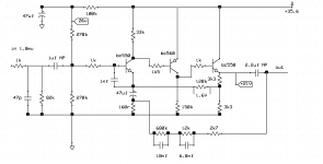
I think this circuit is older than you think - it looks like a very old design from the valve era, very much like somebody took the circuit from a Marantz phono and replaced the valves with transistors.
I may be able to help with the comparison as this one looks like it could knocked up on bread-board fairly easily - my current phono project is ready for testing soon, it is based on the NAD 3020 - it's more complex than this one as it uses 5 transistors instead of 3 - I don't know if anybody would call it a 'boutique' design though, but it is well known and always had very good reviews.
Shameless plug: http://www.diyaudio.com/forums/soli...rid-amp-inspired-hugh-dean-2.html#post4771714
A design that old would have all npns... Still being made today, btw, e.g. the trusty TC-750. Can't say the buffer outside the feedback loop in that one is entirely ideal but still...I think this circuit is older than you think - it looks like a very old design from the valve era, very much like somebody took the circuit from a Marantz phono and replaced the valves with transistors.

I ve been looking for something like that for a very long time simple but effective and well sounding
What actually got me into it was that i looked at the schematic and found resistor values outside of the normal values ...pretty strange for that era
We all know that in this case you either have to play with capacitors which have an issue with accuracy, hard to find if not in a "normal" value and eventually cost too much
or the resistors which one way or another are alike though far cheaper .
At the time high precision resistors/ and values was also one issue
Point is that if a designer placed the company in such a trouble ( IE find , produce or pay resistors outside the "normal" values mean that his product was a result of a very good study and nothing made in a rush ....
Usually designers go for accuracy and precision on paper and their product gets messed up at the factory due to cost reduction ...so 160 R resistor becomes 150 since this is available ....
Kind regards
Sakis
I think this circuit is older than you think - it looks like a very old design from the valve era, very much like somebody took the circuit from a Marantz phono and replaced the valves with transistors.
I may be able to help with the comparison as this one looks like it could knocked up on bread-board fairly easily - my current phono project is ready for testing soon, it is based on the NAD 3020 - it's more complex than this one as it uses 5 transistors instead of 3 - I don't know if anybody would call it a 'boutique' design though, but it is well known and always had very good reviews.
Shameless plug: http://www.diyaudio.com/forums/soli...rid-amp-inspired-hugh-dean-2.html#post4771714
Time era matches the case, though upon first built all voltage is working correctly and it doesn't appear to have any issues at all ...So if this is the scenario the guy who did it had done a good and delicate job ...Choice of parts says so also ...
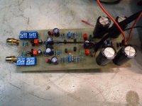
Did some in/out capacitor mix matching just to find a better choice ...regarding quality .
Listening for a couple of days with a very wide variety of cartridges and available turntables and i am falling in love with it ..by Monday detailed measuring will take place which is a thing that i am skeptic about :
IE i trust my ears i know when a thingy plays well small question about the gain is in the air ( might be a bit too much ) and i need to analyze that versus noise.
Though something is telling me that if i find mistakes in it and correct them the sound will never be the same . We will see about that also ....It will require hours on the analyzer and a lot of work but i expect to be done in a week's time .
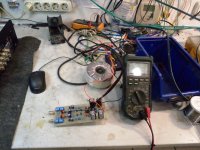
As we speak the board is simply thrown on my bench no shielding at all, leads are too long, together with a million other things running around, and at least 30 fluorescent tubes near me PL type and /or LED's that work with switching power supplies.
Still i can hit the volume of my amplifier at 100% and i hear absolutely nothing from noise or his ....Cannot understand that especially when i know that gain of the circuit is a bit more up than the standards .
I will continue testings
Best regards
Sakis
Attachments
Hannes Allmaier showed an updated version in his High Octane Phono preamp article in Linear Audio Vol 6.
0.99 gets it: https://linearaudio.net/articles?f[0]=field_subject%3A457
Jan
0.99 gets it: https://linearaudio.net/articles?f[0]=field_subject%3A457
Jan
That is interesting Jan thanks
You are going to make me look at Quad schematics and why not make a comparison
Let us not forget that this circuit belongs to a European designer . I will have a look and post back here ...
Kindest regards
Sakis
You are going to make me look at Quad schematics and why not make a comparison
Let us not forget that this circuit belongs to a European designer . I will have a look and post back here ...
Kindest regards
Sakis
Ah yes, I'd forgotten about those anti-matter valves that emit positrons from their heated anode, and collect them on the cold, negatively charged cathode (which Americans still call the "plate"). Those would be the valves that were replaced with PNP transistors. 😀...it looks like a very old design...somebody took the circuit from a Marantz phono and replaced the valves with transistors.
I have a dim memory of a Phillips electronics book I found at my local library when I was a young boy. I think the book had a copyright date from somewhere around 1970, give or take a few years. It was full of similar circuits to the one being discussed in this thread.
That book had "Hi-Fi" in the title, and as the book's introduction went to some pains to explain, all the circuits in the book were designed to meet acceptable Hi-Fi standards, including a maximum of 0.1% THD, and 20 Hz - 20 KHz bandwidth, within +0, -3 dB.
All the small-signal circuits in that Phillips book were built around BC147/148/149 and BC 157/158/159 silicon epitaxial small-signal transistors, which are quite closely related to the BC550 / BC560 transistors in the phono amp being discussed here. Some aspects of circuit topology were similar too, with DC feedback to stabilize operating points, and AC feedback to stabilize gain.
Wikipedia says the BC147/157 plastic-encapsulated transistors were manufactured starting in 1966, so my memory of the book copyright date being circa 1970 is at least plausible.
So, while I don't know exactly how old this particular phono amp design is, I would say it has roots going back more than four decades, and maybe five. 😱
-Gnobuddy
I have a dim memory of a Phillips electronics book I found at my local library when I was a young boy. I think the book had a copyright date from somewhere around 1970, give or take a few years. It was full of similar circuits to the one being discussed in this thread.
Here's the tube version of that book, can't find a transistor one.
http://www.introni.it/pdf/Rodenhuis - HiFi Circuits.pdf
Last edited:
Fascinating! I never saw the tube / valve version until now. I suppose the transistor version I saw was the "new and improved" replacement for the former book, with the then brand-new silicon transistor technology.Here's the tube version of that book, can't find a transistor one.
It's been a long, long time since I last saw that book. But I have a dim visual recollection of a mostly off-white hard-cover book, with maybe red or dark-orange lettering on the cover. But it's been so long that I have no idea if that memory is even real, or I'm just imagining things.
I do remember that the book contained a number of two-transistor "Hi-Fi" preamp circuits, all using a DC feedback loop to set operating points, and an AC feedback network to set voltage gain. These days we would find the overload margins, open-loop gains, and closed-loop distortion levels of those circuits unacceptably bad. But at the time, they were a distinct step forward.
The book also contained a number of power amp circuits of numerous wattages, ranging from 10 watts up to maybe 40W. All the power amps had relatively modern topology (i.e. very different from valve designs); they had complimentary or quasi-complimentary, transformerless, output stages, DC coupling through most of the power amp (though often not to the speaker), and so on. No current-mirrors to be seen anywhere, however!
I had already seen plenty of older transistor circuits by then (I started very young), and the Phillips ones were clearly something new and improved. The older germanium transistor based circuits really did look very much like valve circuits, with the power supply voltage lowered, and the polarity reversed to accommodate the PNP germanium transistors. But these new circuits, designed around low-leakage, high beta silicon transistors, were a big step forward into new and exciting technology.
It's quite ironic that, all these decades later, nostalgia has nudged someone to take the trouble to scan the older valve-based volume into PDF format, but the new and improved semiconductor volume has been (maybe) lost to history!
-Gnobuddy
There are schematics and some discussion of one of the old Phillips preamp circuits, and a matching 40-watt power amp, in this DIY Audio thread (schematics in post #14):
http://www.diyaudio.com/forums/soli...ersal-preamplifier-circuit-2.html#post2645515
-Gnobuddy
http://www.diyaudio.com/forums/soli...ersal-preamplifier-circuit-2.html#post2645515
-Gnobuddy
Now i am going to threadjack my own thread but this is what diyaudio is about : Having fun and learn a few things ...Bare with me might be long .
We have seen plenty of 317 around ...Ancient IC will produce almost any voltage to supply our circuits ...Ideal when the rail (s) is 19.6, adjustable, tolerant and with some interesting other features like safety thermal protection and so on and on .
So 317 is ideal solution for having very accurate rails while easy to implement ... Keeping it clean though is a totally different task before and after regulation while implementing it properly will also require other type of skills .
What i am trying to say is that we have seen 317 used with very low part count near them and even far less behind them ... Now from that till shunt regulators i see a HUGE gap . It seems that people missed all the nice tricks and dirty secrets we have learned from consumer audio from Japanese or the English about regulation or implementation, Luxman and Pioneer with zener fet and transistors , Nad and Harman Kardon with implementation of the local regulation by circuit and many many more .
I like to squeeze the best of a given circuit like i did for the P3A later with P37 which actually is worthless or as good as any other line stage if capacitors are not of some quality , if transistors are not matched and selected , if power supply is not good enough for the application and finally if implementation of all is not up to the task ...That will include PCB design and structure of the "product" together with a proper input selector.I hate when ppl present simulation results from a circuit ...What really matters to me is measuring of the circuit after implemented This is what counts simulation is good enough to calculate electric situations. Just an indication..The actual "product" will be way far from that .
A BC557 C to use in a phono stage that has hfe of 750 is not a device that will play magic ....It's a device that failed in production and produces that much hfe ( as an example ) ....so selecting parts is very critical .
Let us not forget that in the beginning was just a calculated resistor and a capacitor from main rail then Japanese got away with it with a zener and a transistor and often one fet .English got away with it with just a resistor and a zener ...We should be far from that now days shouldn't we ?
So sorry Jan there is not going to be a shunt regulator for me yet ..a well implemented 317 will do as well Also there is not going to be any Jfet in my input ...
Jfet circuits as phono stages i tried many also had the chance to listen to them in many Yamaha amplifiers/preamplifiers while at repair.
Alike B1 it seems that their sound is very very smooth but still the impression is that they tend to round edges and remove punch out of the system.
Of course i remind you that i am into soulful house music ( please fellow "rock" Americans or "only middle" English friends understand this type of music before commenting ).
That will mean that except electronics in this music you have many productions that have real instruments and of course you need your drums to have depth and air your high's to be almost spacy while remain extremely clean, linear and with as much bandwidth possible, while your vocals should be punchy and upfront ...This is a 3D demanding music and ideal for testing circuits to my understanding and taste .
So bjt for me with LM 317...
End offtopic
Enjoy
Best Regards
Sakis
- Status
- Not open for further replies.
- Home
- Amplifiers
- Solid State
- Phono stage from the past ....