Pass uses one CL60 for each 110/120Vac primary.
If you are on a 220/240Vac supply you would get the same soft start limiting effect by using two CL60 in series for a 220/240Vac primary.
You have to decide what level of limiting you require to allow your close rated mains fuse to survive repeated cold starts.
If you are on a 220/240Vac supply you would get the same soft start limiting effect by using two CL60 in series for a 220/240Vac primary.
You have to decide what level of limiting you require to allow your close rated mains fuse to survive repeated cold starts.
Help on the wire twists and eventual grounding problems
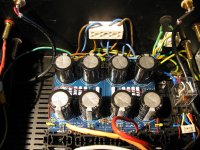
my rca in wire is solid coper from ethernet cable, twisted with isolation. same lenght. is it ok?
my v+(yellow)/v-(purple)/gnd (black) is stranded coper and i tried to twist them on one channel only to have your opinion. (GND wire is thicker)
i Have the transformer secondaries twisted...don't know if i have to do it or not...just in case.
My output (speaker) wire is not soldered because i don't know if i must get the GND from the amp pcb or from the PSU to the Speaker.
thank you
sorry for the pic orientation - can't make it right
An externally hosted image should be here but it was not working when we last tested it.
my rca in wire is solid coper from ethernet cable, twisted with isolation. same lenght. is it ok?
my v+(yellow)/v-(purple)/gnd (black) is stranded coper and i tried to twist them on one channel only to have your opinion. (GND wire is thicker)
i Have the transformer secondaries twisted...don't know if i have to do it or not...just in case.
My output (speaker) wire is not soldered because i don't know if i must get the GND from the amp pcb or from the PSU to the Speaker.
thank you
sorry for the pic orientation - can't make it right
Last edited:
RCA is OK
Your V+ and GND are not twisted properly, look at the black wire from PCB to PSU boards: it's a straight line, not even bended.
Transformer secondaries is OK.
Use the GND from the Amp PCBs.
Nice build!
Your V+ and GND are not twisted properly, look at the black wire from PCB to PSU boards: it's a straight line, not even bended.
Transformer secondaries is OK.
Use the GND from the Amp PCBs.
Nice build!
I think it is much better to take the power leads to connector blocks then to the Amp boards. That way it is simple to isolate each board to do initial bias and set up.
At first switch on you do not want to be looking at both boards.
Un-soldering wires is a pain!
Mine has no hum or noise.
At first switch on you do not want to be looking at both boards.
Un-soldering wires is a pain!
Mine has no hum or noise.
Attachments
Last edited:
RCA is OK
Your V+ and GND are not twisted properly, look at the black wire from PCB to PSU boards: it's a straight line, not even bended.
Transformer secondaries is OK.
Use the GND from the Amp PCBs.
Nice build!
Thanks!
So, the bias procedure was nice and smooth. i have little voltage flutuation. Don't know if this is ok. i am very happy with the sound. I just have two questions:
1- i have hum (i think from the toroid) but it is only audible when i have my ear 1 inch close to the speaker. if i lean back and stay 5 inch close its almost inaudible. At my seat i don't hear anything. Advice needed if you encounter anything wrong in my build. picture attached.
2- I have my P3 pots at middle point but i want to really understand whats going on in terms of THD in my amp. I don't have the gear to measure this but i saw people adjusting the amp to the 2nd or 3rd order harmonic with computer gear and software. I just don't know what to use here and how can i interpretate the results. I saw the video that 6L6 posted but that is with proper gear. Maybe with some help i could make a guide and share it with the community. the information is everywhere but it's really dificult to articulate it without the knowledge needed. Sorry for bothering you all.
have a nice day
Joca
An externally hosted image should be here but it was not working when we last tested it.
An externally hosted image should be here but it was not working when we last tested it.
hi, what Capacitors should i use for the PSU? 15000uF or 33000uF or other values?
Also can a IRFP9240PBF be used? http://nl.mouser.com/Search/Refine.aspx?Keyword=irfp9240
also looking into this transformer:
http://www.toroidal-transformer.com/shop/toroidal-transformers/300va.html
or
http://www.toroidal-transformer.com/shop/toroidal-transformers/500va.html
any advice?
Also can a IRFP9240PBF be used? http://nl.mouser.com/Search/Refine.aspx?Keyword=irfp9240
also looking into this transformer:
http://www.toroidal-transformer.com/shop/toroidal-transformers/300va.html
or
http://www.toroidal-transformer.com/shop/toroidal-transformers/500va.html
any advice?
Last edited:
Four of the 15K uf per rail will work great. More is considered better. I have also used three 22K uf per rail in some builds.
300VA is adequate. Many agree that more is better. I now use 300VA when I can because they are smaller.
Four of the 15K uf per rail will work great. More is considered better. I have also used three 22K uf per rail in some builds.
thanks, and the voltage? 25V okay?
thanks, and the voltage? 25V okay?
If you're buying new ones, go for the 35 V rating.
If you're buying new ones, go for the 35 V rating.
thanks.
found these.
15000UF/35V 30X40MM RM10 PANASONIC ETSF15E ECOS1VP152DA
22000UF/25V 25X50MM RM10 PANASONIC ETSF22D ECOS1EP223CA
22000uf-35v Snap-in Jamicon (by this brand doesn't ring a bell)
thanks.found these.
15000UF/35V 30X40MM RM10 PANASONIC ETSF15E ECOS1VP152DA
22000UF/25V 25X50MM RM10 PANASONIC ETSF22D ECOS1EP223CA
22000uf-35v Snap-in Jamicon (by this brand doesn't ring a bell)
Aluminum Capacitors | Capacitors | DigiKey
These are rated for 3000 hours and are lower priced. http://www.digikey.com/product-detail/en/nichicon/LLS1V223MELC/493-6164-ND/2548942
Last edited:
thanks, didn't find them at digikey...................don't no why..........but now i see them, thanks.
i'll go shop at digikey
i'll go shop at digikey
thanks, didn't find them at digikey...................don't no why..........but now i see them, thanks.
i'll go shop at digikey
Even if you don't buy them there, it's good for looking at options.
thanks for helping.Even if you don't buy them there, it's good for looking at options.
anyone find these at digikey?
Q1 N-Channel JFET Input 2SK170 2SK370
Q2 P-Channel JFET Input 2SJ74 2SJ108
thanks for helping.
anyone find these at digikey?
Q1 N-Channel JFET Input 2SK170 2SK370
Q2 P-Channel JFET Input 2SJ74 2SJ108
Those parts have been obsolete for years. The easiest thing to do is use the LSK170/LSJ74 matched pairs from the diyaudio store.
You can also buy the original Toshiba parts from member Spencer at his FET Audio | Hi-End Audio Projects store.
I would not recommend buying them on eBay.
I would not recommend buying them on eBay.
Last edited:
- Home
- Amplifiers
- Pass Labs
- An illustrated guide to building an F5