Must be sommething wrong with my delay, with 10uf I get 2 minutes maybee better to disable it...
Must be sommething wrong with my delay, with 10uf I get 2 minutes maybee better to disable it...
Yes. Check again careful all value and upc 1237 .
Thanks
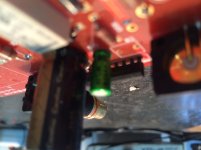
How should upc 1237 be turned,is it the flatside towards the edge of pcb?
See image
Attachments
The DAC is playing (AK4490) allthow the gain is a little to high...
But I must ask again the delay for the relay is waaay to long.....How long is it for you other that have built this?
Hi!
C9 late on duty close to the relay, avoiding audible speaker.
Closing time lag depends on the capacitor C9.
470uF: closing delay of about $ 30.
680uF: closing delay of about $ 45.
very good time for most of the pre tube.
thank you
I´ve changed the UPC1237 to another one and c9 1uf and I get about 1 minute,all components seems right.
excxept I use +F and-F 6,3v instead of 12,6v does it matter for the upc 1237?
Those of you who built the tube output board,what DAC are you using and how is your gain?
The reason I´m asking is I get a little noise (when music not playing) in my 6E6p -->SE EL36 amp and the gain is way to high,I use the Squeezebox Duet and its volume control.I can bearly touch the volume before it gets to high..
How have you managed this?
Edit:I use ECC88 and 12BH7
The reason I´m asking is I get a little noise (when music not playing) in my 6E6p -->SE EL36 amp and the gain is way to high,I use the Squeezebox Duet and its volume control.I can bearly touch the volume before it gets to high..
How have you managed this?
Edit:I use ECC88 and 12BH7
Last edited:
Ryssen: If you are using AK4490 as you told before that is the problem. Because all info i find by googling around is that AK4490 is a voltage output dac, not a current output as this this output stage is supposed to be used with. So your dac shouldn't even use a I/V stage, just a buffer, if anything.
Update:I am now not using the I/V stage on the board just the buffer stage and I is sounding just fine.and the gain is fine to.
Ryssen; excxept I use +F and-F 6 said:Hi Ryssen!
you need 3 pin for it: +F, AC, -F
all now work well ?
thanks
I have the 3 wires:+F, AC ,-F.
Its working but its about 90 seconds,anyway I am satisfied with that..
Its working but its about 90 seconds,anyway I am satisfied with that..
I have the 3 wires:+F, AC ,-F.
Its working but its about 90 seconds,anyway I am satisfied with that..
please down the cap = 470uF, the time about 30 S.
thanks
please down the cap = 470uF, the time about 30 S.
thanks
I´m down to 1uF now =90 sek.. don´t know why..🙄
Due to a very difficult year and a baby on the way I will have to sell my very high end kit. I hope someone here can do this lovely set up justice and that the price is fair:
http://www.diyaudio.com/forums/swap...q-iv-high-end-kit-plus-tubes.html#post4847328
http://www.diyaudio.com/forums/swap...q-iv-high-end-kit-plus-tubes.html#post4847328
I´m down to 1uF now =90 sek.. don´t know why..🙄
i think you wrong .
because, i make many kit, all work well
thanks and check all again
quanghao
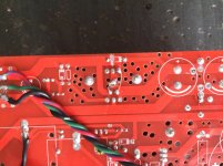
I´m down to 1uF now =90 sek.. don´t know why..🙄
Please check wrong for filament.
Thanks
Attachments
I know it has been sometime, but I have managed to populate the boards. I stii have the same problem as PASSIVE420 with the Power supply. The lv is working, but the 12V I can get is in the edge of the trimmer (I am using the LT1764 regulator). For the HV parte the only output I can get is 154VDC, with 220VAC input. Also the trimmer doesn't seem to modify anything. Passive420 how did you manage with the power source? Thank you.
Last edited:
I know it has been sometime, but I have managed to populate the boards. I stii have the same problem as PASSIVE420 with the Power supply. The lv is working, but the 12V I can get is in the edge of the trimmer (I am using the LT1764 regulator). For the HV parte the only output I can get is 154VDC, with 220VAC input. Also the trimmer doesn't seem to modify anything. Passive420 how did you manage with the power source? Thank you.
I cannot edit the post once more so I post again
I have solved the two problems
For the HV section I had a problem with LM 317. It was somehow out of order. Changed it and the HV part worked as expected.
For the LV part I had to change R13 from 220R to 10k and after this I could fix the LV output to 12V or any other value.
I've just been troubleshooting a low filament voltage, and (quite separately) discovered that the left and right channel input labelling is inverted on different sides of the IV board, i.e. what's labelled left on the bottom is labelled right on the top. Just noting that here in case it catches anyone else out.
I've just been troubleshooting a low filament voltage, and (quite separately) discovered that the left and right channel input labelling is inverted on different sides of the IV board, i.e. what's labelled left on the bottom is labelled right on the top. Just noting that here in case it catches anyone else out.
yes , thanks!
quanghao
- Status
- Not open for further replies.
- Home
- Group Buys
- HQ-IV tube output balance DAC