So before I get to the point of putting the diaphragm on and permanently sticking the panels together..... I have a question.
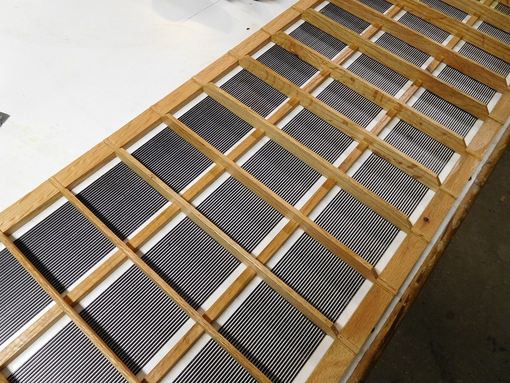
There are spots where the wires are closer together and sometimes touching each other in the stators. Provided this occurs within the same segment I don't see this as a problem electrically but are there any other issues with this problem such as buzzing etc... such that I should take serious efforts to mitigate it (e.g. removing/replacing wires etc...).
Also, given the tolerances.... I can already tell that the front and back wires are not going to align vertically with each other (probably offset by a wire or 2 to the left or right). Is this a problem?
If I had to do it again, I would make them out of metal... Wood moves too much 🙂.
I responded to your question in the Aerius thread.Gents, can I throw in a slightly OT question: what are the typical effects of a diaphragm losing tension? I have a pair of vintage ML Aerius and I find the sound from the panels constricted and much lower in level than the woofer. Should I replace the foil?
http://www.diyaudio.com/forums/plan...erius-no-sound-esl-section-4.html#post4775849
It is much more important to keep the wires in a plane uniformly distanced from the diaphragm, than uniformly distanced from each other. So, I would not recommend attempting to mess with wires to improve visual alignment with adjacent wires as it is likely to mess up the D/S spacing. I doubt touching PVC insulation will result in any audible buzz. If it does, a dot of E600 should cure it.There are spots where the wires are closer together and sometimes touching each other in the stators. Provided this occurs within the same segment I don't see this as a problem electrically but are there any other issues with this problem such as buzzing etc... such that I should take serious efforts to mitigate it (e.g. removing/replacing wires etc...).
Misalignment of wires within a section will not affect the sound. Misalignment of wires where one section of rear stator is overlapping adjacent section from front stator will have minor effect on polar response. In your case, if it is only a wire or two it will be difficult to hear/measure the difference.… the front and back wires are not going to align vertically with each other (probably offset by a wire or 2 to the left or right). Is this a problem? If I had to do it again, I would make them out of metal... Wood moves too much 🙂.
http://www.diyaudio.com/forums/plan...-more-questions-els-design-3.html#post2772574
Must admit though, I am not understanding how/why wood construction would by the cause of wire offset between front and back stators.
If I had to do it again, I would make them out of metal... Wood moves too much 🙂.
Wood is rather finicky but it can work quite well for a stator lattice-- if you start with dry, straight pieces, designed be flexible where needed and stiff where needed, and the wires are relaxed when glued in place. The results will be flat and true.
In my wood stator lattices, the side rails and center supports are fairly thin and flexible. Whereas the horizontal wire supports are quite stiff and very flat across their span (easily within .002). Once the semi-flexible front/rear stators are assembled, they are perfectly parallel, even though they can bend together in the vertical plane. When they are mounted into my speaker's rigid frames, they are then held perfectly straight in the vertical plane also.
Having some experience with woodworking, I offer the following advice for anyone contemplating building wood lattice wire stators:
* If you have no experience working wood and you don't own a jointer and a planar, don't use natural wood. Use a high grade AA plywood instead, as it is perfectly stable (in-plane).
If you have access to a jointer and planar and want to use hardwood:
1) Quarter-sawn wood is far more stable than plain sawn. (a board is considered quarter-sawn if its annular rings are within 15 degrees of perpendicular to its face).
2) NEVER cut a board to net thickness on the first pass thru the saw or planar. Practically all warpage occurs when cutting or planing the board due to internal stress relieving itself. Start with an over-thick board that's wide enough to slice out multiple details. Then "sneak up" on the final thickness in several steps, as described below.
- Joint one face flat by running the concave face across the jointer until that face is perfectly flat.
- Flip the board over and run the opposite face thru the planar; removing only about 1/32" per pass, until you get to net thickness. After each pass, eyeball the board for warpage and if you see any, flip the board over and plane the convex face -- this warps the board in the opposite direction toward flatness.
You have to sneak up on flatness but once you get the board cut flat it tends to remain flat.
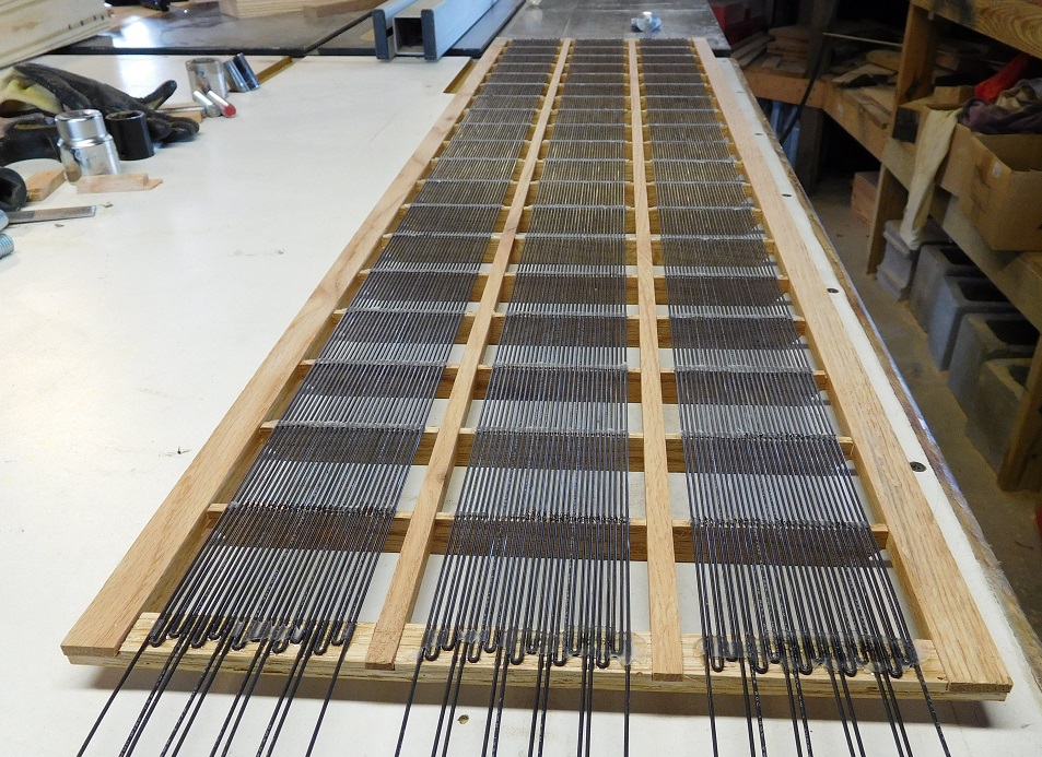
3) Once the board stock is cut to net length and planed to net thickness and flatness, then you can rip out slices for the details. The photo below shows the boards from which I cut my wire support slats from to build my stators. After cutting them to flatness, length and profile, I merely sliced out the 3/16 thick wire supports on the table saw.
4) The side rails and center spacer supports were likewise cut from overwidth boards that were precut to profile. In this way, all pieces are exactly the same thickness and there is no deviation.
5) Finally, the wood lattice was assembled over the wires on a perfectly flat surface covered with wax paper. The end result was stators almost perfectly flat and the wire glue lines were flush with the surface of the wires.

Last edited:
Esp when you have some high frequency EQ, tricky balancing among amp power (when the load impedance can be very low), bias, and playing loud. My amp complains during sweep-tone tests but not with loud music... not sure if this means my treble peaks are also over-the-top (and distorted) on music but too brief to trip the safety mechanisms in the amp.
I dob't have a clear picture of the cause, the measurement, or the sound of changing bias, but would appreciate clarification.
Depending on the time course, changing bias violates the commandments of Hunt!
Mike Wright says output goes up as the square of the bias. But I seem to recall Bolserst doesn't agree.
Ben
Here is a post of what I was referring too, not exactly, but similar.
http://www.diyaudio.com/forums/planars-exotics/190716-esl-power-supply-question-2.html#post3788615
It was during the same tests 3 years prior to this post, there is another post of this from when I first described it back in 2010, But I wouldn't know exactly what key words to search in order to find it.
I was just lucky enough to have found this one. 😉
jer 🙂
Just wanted to check in and let you all know I'm still alive 🙂. Had a bunch of stuff take up my time the last month but still slogging thru my build. Got most of the tedious soldering done, ready to put the membrane on.
I will update with some pictures when I get a little further down the road.
I will update with some pictures when I get a little further down the road.
So another build question....
I am trying to figure out how and where I am going to put the resistor banks for my stators (using ones fabricated by Ken Seibert). Given I have a toddler running around the house etc... I think I am pretty much resigned to having them mounted inside the woofer box. Since I have 19 physical segments, this means I will have 19 X 2 = 38 wires running into the box for each panel.
The question is, can I bundle all the wires from each side of the panel and run them thru 2 separate large holes? Is there any concern for capacitive coupling etc... I need to worry about? Would rather not have to drill 38 (39 really, one for the charge ring) into the top of the woofer "box" and thread them thru.
BTW I am using test lead probe wire rated at 5 kV or so.
On some of my panels I have put the ladder resistors at the top of the panel, with just one wire connecting to the middle segment at the bottom of the panel. This would put your resistor bank out of the reach of toddlers I would think, right?
I have considered that before... basically, the PCB's are so big that I thought the panel would look "wierd" if I added a big 3" wide "header" on top. I will take a look at that approach again though and see if I can make it work.
But do the wires coming off the segments need to be separated? i.e. what is the consequences of having all those wires bundled together and run thru a hole?
But do the wires coming off the segments need to be separated? i.e. what is the consequences of having all those wires bundled together and run thru a hole?
Unrelated to anything, had a random thought as I am applying the VHB tape to the frames......
Since my panels are spaced vertically, I was wondering if there was any value into tensioning the diaphragm at different tension levels in each of the 3 vertical segments? i.e. make the center section at a higher tension than the 2 outer sections etc....
Anyone thought of this or done this? (sure someone has 🙂 ).
Since the bundle length will be pretty short, and 5kV insulation is thick I don’t think there is concern for substantial capacitive coupling between wires. However, the voltage between wires may be of concern if it is above the corona generation threshold for your wire. I know Acoustat had issues with this on their segmented Spectra models and used PVC tubes to ensure wires were separated.… can I bundle all the wires from each side of the panel and run them thru 2 separate large holes? Is there any concern for capacitive coupling etc... I need to worry about? …I am using test lead probe wire rated at 5 kV or so.
http://www.diyaudio.com/forums/planars-exotics/183168-acoustat-answer-man-here-129.html#post4263148
Looking back at Post #181 you can see the voltages across your ladders resistors; voltage from wire to adjacent wire would be the same. But, if Wire #1 was next to wire#10 in the bundle you could easily get 2kV or more between them. I don’t know if this would result in corona/ozone generation with your particular 5kV wire or not. You could run a test by twisting two runs of the wire together and feeding it the output of your 129:1 step-up transformer setup @ 200Hz – 300Hz and see at what voltage(if any) corona becomes visible and/or you smell ozone. See pics #1 and #2 for similar test on transformer wire here:
http://www.diyaudio.com/forums/plan...up-measurements-part-1-2-a-3.html#post2861741
Rather than drill separate holes, could you cut a slot just wider than the wire diameter and then position the wires in segment order so as to minimize voltage differences between the wires?
Staggering the tensions between adjacent sections can lower the overall Q of the resulting response peak, but not so much that you’d probably notice without careful measurement comparisons. Since you are building a hybrid and plan to cross over above the resonance frequency, probably not worth the effort.…I was wondering if there was any value into tensioning the diaphragm at different tension levels in each of the 3 vertical segments? i.e. make the center section at a higher tension than the 2 outer sections etc....
Last edited:
So now that my stators are complete, I have a question to ask 🙂....
Basically, all of my wire segments touch/lay against the bottom wooden frame rail (they are hot glued down to the bottom rail). Given the stator voltages are reaching thousands of volts, is the wooden frame too conductive? Is this going to cause problems?
The diaphragm itself will be isolated from the wooden frame via with fairly thick polycarbonate spacers...and thus the front and back frames will be *really* isolated from each other with the polycarbonate, VHB tape and mylar "stack".
I don't think it should be a problem.
As long as the diaphragm is well insulated from the wood frame with PC spacers, you shouldn't have issues with undo leakage from the HV supply. The segmentation resistors will be orders of magnitude more conductive than the wood, so that should be a problem either.
Can you post a pic just to be sure the situation is as I am thinking?
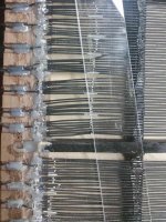
Attached is a picture of where the wire segments are glued down to the frame.
Basically, I think there wouldn't be much of a problem with sound quality, mostly worried about safety... e.g. if you grabbed the side of the frame; is there enough resistance in the wood to drop the voltage down to something extremely safe.
Basically, I think there wouldn't be much of a problem with sound quality, mostly worried about safety... e.g. if you grabbed the side of the frame; is there enough resistance in the wood to drop the voltage down to something extremely safe.
Attachments
One other item for a "gut check". Getting ready to click "buy" on all the electronic parts I need and I noticed for my bias supply, this CCFL inverter says "non-dimming".... which suggests to me it wants around 12V period.
My plan/design was to input a variable amount of DC voltage to adjust the charge of the diaphragm. Is this going to work? i.e. will it take 5V etc???
Here is the part number....
http://www.mouser.com/Search/ProductDetail.aspx?R=CXA-L10Lvirtualkey52130000virtualkey810-CXA-L10L
My plan/design was to input a variable amount of DC voltage to adjust the charge of the diaphragm. Is this going to work? i.e. will it take 5V etc???
Here is the part number....
http://www.mouser.com/Search/ProductDetail.aspx?R=CXA-L10Lvirtualkey52130000virtualkey810-CXA-L10L
The resistance of the wood is going to dependent a lot on the humidity.... mostly worried about safety... e.g. if you grabbed the side of the frame; is there enough resistance in the wood to drop the voltage down to something extremely safe.
To ensure safety, you would probably need isolate the wooden stator from the wooden frame with some PC sheet.
If your stator is mounted in a slot in the frame, you could also use some mylar packing tape or PVC electrical tape .
The "non-dimming" supplies will operate at lower input voltages, and the output voltage is proportionally reduced.I noticed for my bias supply, this CCFL inverter says "non-dimming".... which suggests to me it wants around 12V period.
I know from personal experience that the CXA-L10L will operate on as little as 1.5V.
The "dimming" supplies usually have a digital interface so that a computer can control the dimming of the backlight for a display. Usually this is done with PWM of the output voltage. This will not work for an ESL supply since the output of the multiplier always charges to the peak of the waveform, so the PWM would have no effect.
The resistance of the wood is going to dependent a lot on the humidity.
To ensure safety, you would probably need isolate the wooden stator from the wooden frame with some PC sheet.
Not entirely sure what you mean here.... basically my stators consist of a wood frame with a wood grid (holding the wires) embedded&glued together. "Electrically", they are like Charlie's. The difference is, my segments are soldered together in groups (i.e. exposed wires) and glued down to the frame. Or to say it another way, the wooden frame/grid is energized with HV coming from the transformers.
It is kind of like Ken's here: except where he ends his segments before the wood frame, I overlap mine on the rail and glue them down (for support). http://www.kenseibert.com/esl/images/panelwirefeeds.jpg
Then there are PC spacers that are glued down on top of the frame (and vertical grid), then VHB tape on top of that, will stick it all to the diaphragm.
So when all done, it would be quite easy for someone to grab the side, which would be touching the front and the back stator at the same time.
How much current would be "available" from the HV out from the step up transformers?
Also, just for fun, I stuck the probes of my meter into the wood frame about 1/2" apart and the resistance was in excess of 20 megaohms (out of my meters limit).
I would *think* I would be OK as I would imagine lots of people making these would be getting zapped with perf metal stators glued to wood frames etc...
Lessons learned here is, avoid using wood for the stators 🙂 and using a wire stretcher like you and charlie have leaves the wires in the segments insulated until they are out of the frame.
Last edited:
By frame, I was meaning the outer support structure to which you would be attaching your stators.
Stators often do have their own frame, but usually much thinner and not strong enough to stand vertical on their own.
I agree that it is not likely going to be a problem.
Stators often do have their own frame, but usually much thinner and not strong enough to stand vertical on their own.
I agree that it is not likely going to be a problem.
By frame, I was meaning the outer support structure to which you would be attaching your stators.
Stators often do have their own frame, but usually much thinner and not strong enough to stand vertical on their own.
I agree that it is not likely going to be a problem.
Ah, I see... my plan is to make them kind of like Sander's ESLs (well, the older models anyways)... Charlie has provided me with a set of plans and after I figure out how to scale them/change the dimensions in CAD to fit my panel width 🙂, I plan to use them.
My panels are pretty stiff. Each frame is 1/2" thick so they will be over 1" thick (w/spacers) when all put together.
Wondering if anyone has any advice on this....
I need to cut 1/2" wide polycarbonate spacers for the grid part of my panels.
Any recommendations on how to cut it? So far, tin snips seems to be the "best" way but not ideal.
Tried, my tablesaw, a diamond blade wet saw and just scoring with razor and snapping it off..... none of that worked well 🙂
I need to cut 1/2" wide polycarbonate spacers for the grid part of my panels.
Any recommendations on how to cut it? So far, tin snips seems to be the "best" way but not ideal.
Tried, my tablesaw, a diamond blade wet saw and just scoring with razor and snapping it off..... none of that worked well 🙂
- Home
- Loudspeakers
- Planars & Exotics
- About to take the ESL plunge