I assume you are talking about the phase shift from 0 to -180 at the upper bandwidth limit?
If so, the only way to correct it is extend the upper bandwidth limit, or use a digital filter to fix the phase. There is nothing unusual about ESLs in this regard. Pretty much every loudspeaker has a second order(or higher) LP behavior just above the audio band.
So that would be a good reason to wire up the transformers in 2nd configuration (the more "complicated" one) to extend the upper bandwidth?
Isn't this "usually" corrected (only improved really) by reversing the phase of the tweeter in conventional speaker designs? I know I have done this a few times in speaker builds I've done in the past. That is kinda what I was driving at. e.g. if I reversed the phase on the stator in the center segment(s) that is producing that upper frequency band.
Not sure, but maybe the Audyssey room correction technology in my preprocessor would digitally "fix" this??
(I swear everyday I learn something new in this forum 🙂 ).
Need some advice here....
So I will need to "affix" some polycarbonate spacers to the perimeter of my stator frames and to the vertical grids.
What works well to glue polycarbonate to wood? I was thinking good ole fashioned 2 part epoxy (which I already have plenty of in my shop) or something more purpose built exotic stuff like Weld-on 16 acrylic glue (not sure how well it bonds to wood though).
BTW I am alotting about 20 mills (.02 in) of added thickness due to the glue.
Yes, anything you can do to extend the upper bandwidth limit will minimize the phase shift at 20kHz.So that would be a good reason to wire up the transformers in 2nd configuration (the more "complicated" one) to extend the upper bandwidth?
To keep things in perspective though, this slow phase shift at the upper bandwidth limit is just not something to lose sleep over. Every speaker you have ever listened to (unless corrected with digital filters) has it, and your ESL will have less of it than most.
No. Reversing the phase of a tweeter is to compensate for difference in acoustic center between the tweeter and woofer, effectively delaying the tweeter by 1/2 wavelength in the frequency range of the crossover. In some cases, even when acoustic centers are aligned with a stepped or slopped baffle, reversing the phase of the tweeter may be required to compensate for phase shift resulting from the crossover filters themselves. In either case, it does nothing to change the phase shifting due to the tweeter response roll off above 20kHz.Isn't this "usually" corrected (only improved really) by reversing the phase of the tweeter in conventional speaker designs? I know I have done this a few times in speaker builds I've done in the past. That is kinda what I was driving at. e.g. if I reversed the phase on the stator in the center segment(s) that is producing that upper frequency band
The center segment of a segmented ESL is not analogous to a tweeter. It operates over the whole frequency bandwidth, not just the highs. If you reversed its polarity, you would actually cause more/faster phase shift as well as putting a -6dB dip in the upper octaves and shelving down the entire response by -2dB because the output from the center segment would be cancelling out(rather than reinforcing) the output from all the other segments.
No. You would need a dedicated DSP processor.Not sure, but maybe the Audyssey room correction technology in my preprocessor would digitally "fix" this??
There is a current thread on the topic of linearizing phase with free software here:
http://www.diyaudio.com/forums/mult...zation-eq-fir-filtering-tool.html#post3199084
Polycarbonate is a fairly high surface energy plastic, so standard epoxy adhesives should work fine...What works well to glue polycarbonate to wood? I was thinking good ole fashioned 2 part epoxy...
Roughen up the surface of the polycarbonate with some sandpaper before gluing to improve bond strength.
I'd say give the epoxy you have on hand a test with some scrap material.

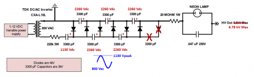
So attached is the schematic for my bias supply.
The datasheet (such that it is) states the output is 800 Vrms.... not sure what the frequency is. I am expecting a max of somewhere around 6 kV output. This might be wrong though as I think peak voltage is something like 1.4 * Vrms.... this would put it closer to 8 kV.
Not entirely sure I need the 220k resistor going in, as the datasheet states the output current is 5ma so it might be "overkill". But I suppose it still might be a good idea so it doesn't accidentally "overkill" me 🙂.
Attachments
Last edited:
Do you have panels?...
Yes, working on final assembly of them now.
Correct. With 800Vrms output, the first cap will charge to peak of sine wave which is 800 x sqrt(2) = 1130Vpeak. All the following caps will charge to 2 x Vpeak. Note that the last diode and cap are being charged but not contributing to the output so you can delete them....This might be wrong though as I think peak voltage is something like 1.4 * Vrms.... this would put it closer to 8 kV.
The 5mA spec is the max output current the module is designed for. You will only be drawing few microAmps at most. The 220K resistor is mainly there to protect the CCFL module in the event something in the HV section shorts.Not entirely sure I need the 220k resistor going in, as the datasheet states the output current is 5ma
Attachments
Question for you guys...
As I am assembling my stator panels, I am noticing they are not perfectly flat. i.e. the bow in/out in the middle a bit (maybe 1/16" or so) when you lay a straight edge down their length (1/16" or so).
Should I be panicked about this? 🙂. I would think the spacers are going to keep me out of too much trouble and given the tolerances of woodworking in general, wood will twist, warp etc.... at least 1/16" over 4 feet, my experience anyways.
Just want to make sure I am not missing something.
Question for you guys...
As I am assembling my stator panels, I am noticing they are not perfectly flat. i.e. the bow in/out in the middle a bit (maybe 1/16" or so) when you lay a straight edge down their length (1/16" or so).
Should I be panicked about this? 🙂. I would think the spacers are going to keep me out of too much trouble and given the tolerances of woodworking in general, wood will twist, warp etc.... at least 1/16" over 4 feet, my experience anyways.
Just want to make sure I am not missing something.
The panel can be warped as long as the front and back stators are parallel to each other such that the d/s is relatively constant. Any area where the d/s is significantly closer would be prone to driving the diaphragm into a stator; whereas, any areas where the d/s is significantly wider would have reduced output.
If your panel uses vertical center support spacers (like mine) and the front and rear spacers are in intimate contact as they should be, I don't think you will have any problems, even if the panel has some warp or twist.
Last edited:
Thanks,
I am hoping the VHB will "suck" the panels together and make them fairly parallel....but it will only be as strong as the weakest link, which will be the epoxy joint holding the polycarbonate spacers to the frame/grid.
Also, I want to vouch for something I saw posted on here somewhere about heating up nippers with a torch (or whatever) to strip the wire ends. I can say it works *quite* well. Makes stripping the wire ends of nearly trival.
Curious about this.... I've tried searching for this without much luck but what is the equation/calculation to determine the excursion of the diaphragm? e.g. say a 250 hz sine wave @ 100 SPL?
Just curious how small the gap could be without banging into the stators.
Just curious how small the gap could be without banging into the stators.
This small amount of bowing should not be a problem, as long as the front and rear stators stay stuck to each other along all of the spacers.... I am noticing they are not perfectly flat. i.e. the bow in/out in the middle a bit (maybe 1/16" or so) when you lay a straight edge down their length (1/16" or so)...
The equations for determined peak diaphragm excursion for an ESL of a given area to output a desired SPL are fairly straight forward..... I've tried searching for this without much luck but what is the equation/calculation to determine the excursion of the diaphragm? e.g. say a 250 hz sine wave @ 100 SPL?
An example for 120dB @ 1m was posted here:
http://www.diyaudio.com/forums/planars-exotics/181725-dayton-wright-xg-10-a-2.html#post2446978
I considered including an excursion estimator in the Segmented ESL spreadsheet, but decided not to as it would probably cause more confusion that anything for the following reasons.
1) Besides the peak side-to-side excursion required for producing sound(easy to calculate), there is a steady offset that is dependent on diaphragm tension, bias voltage, leakage resistance, and unsupported width(difficult to calculate). The steady deflection is typically about 10% - 20% of the gap.
2) Even if you don't need much excursion capability for >200Hz, you will need a gap big enough to handle excursion at the diaphragm resonance which can be considerable even if crossed over sharply.
3) The diaphragm does not move with uniform excursion everywhere. The steady deflection is also greatest in the middle of the unsupported width.
Thanks... I see that the excursion for my panel will be much less than .03 inches to produce 100 dB or so.
As it stands with the spacers, tape thickness etc... I will have a spacing of about .07 inches. I had an option to go with something like .05 spacing but decided on the larger gap to accommodate the Fs of the panel and the massive subwoofer I have in the room (I built as well) for LFE stuff.
So, unrelated but interesting (to me anyways) is I am circling down on getting my resistor bank/values in order. I find it interesting that a change of .01 in d/s results in a 10K ohm change in resistor requirement for the segment.
I am kind of curious if it is possible to just assemble the panel and measure the capacitance (if even feasible) of each segment THEN calculate the resistor value you need. With all the construction tolerances, wires not perfectly spaced etc... etc.... I suspect the actual capacitance of the segments vary wildly from the theoretical value.
Not sure if this is even worthwhile as I am not sure how "sensitive" the resistor value is to the response. e.g. if the spreadsheet tells me to put in 50K and I put in 65K what would happen?
Gents, can I throw in a slightly OT question: what are the typical effects of a diaphragm losing tension? I have a pair of vintage ML Aerius and I find the sound from the panels constricted and much lower in level than the woofer. Should I replace the foil?
Jan
Jan
Ok, another question....
It is getting time to stretch and apply the diaphragm. I am considering "heat treating" the mylar by going over it with a heat gun whilst it is stretched.
The question(s) I have are:
Is it even worth doing? I am trying to minimize the "creep" of it relaxing over time. After reading this post (and a few others like it) seems like there isn't much advantage to doing it. http://www.diyaudio.com/forums/plan...-more-questions-els-design-8.html#post2811884
If I do it, do I tension it to 1.75% then apply the heat gun or do I go low, like 1% then apply heat to get it to tension up to a higher value?
BTW, I am trying to get an Fs of no more then 120hz.
Last edited:
Ok, another question....
It is getting time to stretch and apply the diaphragm. I am considering "heat treating" the mylar by going over it with a heat gun whilst it is stretched.
The question(s) I have are:
Is it even worth doing? I am trying to minimize the "creep" of it relaxing over time. After reading this post (and a few others like it) seems like there isn't much advantage to doing it. http://www.diyaudio.com/forums/plan...-more-questions-els-design-8.html#post2811884
If I do it, do I tension it to 1.75% then apply the heat gun or do I go low, like 1% then apply heat to get it to tension up to a higher value?
BTW, I am trying to get an Fs of no more then 120hz.
If you stretch 6-micron film to 1.75% elongation, I suspect it would actually LOSE some of that tension if heated.
If the span between your spacers is not greater than 4 inches, then 1.5% elongation is probably enough.
And I don't think you need to worry about the diaphragm losing tension over time. It will lose a small amount initially and then stabilize for many years.
Last edited:
If you stretch 6-micron film to 1.75% elongation, I suspect it would actually LOSE some of that tension if heated.
And I don't think you need to worry about the diaphragm losing tension over time. It will lose a small amount initially and then stabilize for many years.
You're right about it losing tension....
I was thinking of just putting it on the jig, apply a *little* tension to take the wrinkles out... go over it with a heat gun *then* stretch it my final 1.75%.
I've been puzzling about heat shrinking for the last 40 years.... and really don't know except to say, I've never harmed a Dayton-Wright cell in my DIY panels with modest amounts of heat.
The problem, as in other cases with ESLs, is the challenge of measuring or otherwise observing what you are doing. So for you, Step One would be setting up the panels in the light so you can see their shimmering surfaces clearly.*
Ben
*Hint for those who lose sleep about beaming: that's how I set up my panels so they are pointing straight to my seat. Hold a lamp on your head.
Hi,
I typically get ~10% fs reduction when stretching to 1.5-2% (depending on film thickness and film quality) and heat treating, against mechanical tensioning only.
As described in that earlier linked thread, tension very hard and heat treat at least once and leave it there.
Fs constancy will be very good and the panel plays as intended from the first note and doesn't change for years.
I'd forget about pretensioning, heating, re-tensioning.
Rather use more than one heating cycle than mechanical tensioning cycle.
jauu
Calvin
Absolutely, if you have an LCR meter that can measure in the pF range accurately.I am kind of curious if it is possible to just assemble the panel and measure the capacitance (if even feasible) of each segment THEN calculate the resistor value you need. With all the construction tolerances, wires not perfectly spaced etc... etc.... I suspect the actual capacitance of the segments vary wildly from the theoretical value.
The best method is to measure the capacitance of the entire panel by connecting all the segments together. Then, for modeling purposes, adjust the gap dimension in the spreadsheet until the total capacitance value matches what you measured. But sure to set the height and width = the area covered by your stator wires. I generally find good agreement(+/-10%) between measured and modeled panel capacitance.
If you increase R, the fL and fH breakpoints will shift to the left (ie reduce in frequency); also the midband sensitivity will drop a bit. If you decease R, the opposite happens. You can observe this behavior by adjusting fL and note the changes in fH, R, and midband sensitivity.Not sure if this is even worthwhile as I am not sure how "sensitive" the resistor value is to the response. e.g. if the spreadsheet tells me to put in 50K and I put in 65K what would happen?
Quantitatively…
If you double R: fL and fH are halved, sensitivity drops by -3dB
If you halve R: fL and fH are doubled, sensitivity increases by +3dB
Last edited:
- Home
- Loudspeakers
- Planars & Exotics
- About to take the ESL plunge