Hi Bengel,
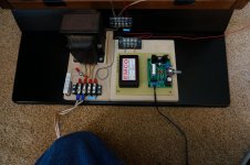
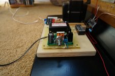
Like Bentoronto, I use an EMCO module for the bias supply on my stats. Mine is an F40 that I bought on EBay for $55 but the same seller also has some 'B' stock models for only $40. The LM317 variable power supplies can be purchased through Amazon for around $11. While not inexpensive, it makes for an easy to build neat looking adjustable bias supply. Below are a couple of pictures.
Bondsan
Attachments
I prefer a regulated supply.
I built my own and if you are up to the task checkout this thread,
http://www.diyaudio.com/forums/plan...tor-insulation-mylar-coating.html#post2848194
It may be overkill, but it is rock solid !!
The highest limit that you can go depends on the quality of your insulating materials.
I have run up to +10Kv (13.8Kv is the most my supply will do), But above 8Kv it started to reek havoc on my test panels at the time since they weren't designed to go that high in the First place.
But at 12Kv the efficiency was incredible !!!!
The amp I was using loved this since I didn't have to drive it hard at all ! 🙂
I used a true regulated feedback system because I had found while I was designing this supply that at higher levels the Bias voltage was being modulated on extreme excursions of the diaphragm.
I could hear this on some material as the voltage would drop considerably causing a form of compression.
I noted as much a 500v and sometimes a peak of 1Kv of voltage change using my scope to monitor the voltage.
Even though 200v to 500v doesn't seem like much but it is as much as 10% on most setups.
It is common to use the cheaper Emco stuff and this method could be easily adapted to them.
Many of the CFL power supplies are of the same design as mine and I plan on getting one and build a newer version to show for the average DIYer too easily build.
FWIW
jer 🙂
Last edited:
I used a true regulated feedback system because I had found while I was designing this supply that at higher levels the Bias voltage was being modulated on extreme excursions of the diaphragm.
I could hear this on some material as the voltage would drop considerably causing a form of compression.
I noted as much a 500v and sometimes a peak of 1Kv of voltage change using my scope to monitor the voltage.
Even though 200v to 500v doesn't seem like much but it is as much as 10% on most setups.
Esp when you have some high frequency EQ, tricky balancing among amp power (when the load impedance can be very low), bias, and playing loud. My amp complains during sweep-tone tests but not with loud music... not sure if this means my treble peaks are also over-the-top (and distorted) on music but too brief to trip the safety mechanisms in the amp.
I dob't have a clear picture of the cause, the measurement, or the sound of changing bias, but would appreciate clarification.
Depending on the time course, changing bias violates the commandments of Hunt!
Mike Wright says output goes up as the square of the bias. But I seem to recall Bolserst doesn't agree.
Ben
This post will be a summary of some tests I ran on 4 of bengel’s VTX transformers earlier this month....My transformer step up is 129:1 (more to come on that, BTW)…
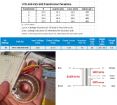
Attachment #1: Preliminary tests to determine step-up ratio and individual transformer parasitics. The step-up ratio of 32.2:1 is less than the expected 38 = (230/6). This is because the smaller gauge wire used in these lower wattage transformers results in voltage loss due to winding resistance when operating at rated current. To compensate, more turns are used on the 6Volt windings than would be the case with heavier gauge windings. Notice the 16% regulation mentioned in the spec. This means that with no load, the output voltage would be 7Vac instead of 6Vac. This specification would suggest a winding ratio of 32.9 = (230/7). Actual measurement showed 32.2:1.
Phasing of the windings matched dot notation provided on the spec sheet.
Parasitics for the 4 transformers were reasonably uniform.

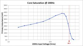
Attachment #2: I checked the voltage handling capability at 200Hz by measuring inductance as a function of input voltage. The 100 turn primary provided a nice high primary inductance which will allow parallel operation of 4 transformers without the impedance dropping unacceptably low. Notice also the rule of thumb that power transformers tend to be operated 15% below core saturation levels holds true for these toroids.
6Vac x (1.15) x (200Hz/50Hz) = 27.6 Vac
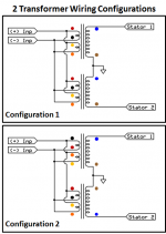
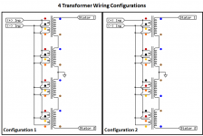
Attachment #3 - #4: When testing 2 and 4 transformer configurations, it was noticed that using the brown wire ends of the secondary winding to form the CT resulted in lower winding capacitance. This is not unexpected since the 3220 turn secondary on this small core would need to be multi-layer and one end will be closer to the primaries than the other. Wiring that end as the CT results on lower winding-to-winding voltage and thus capacitance. In any case, you can take advantage of this by using Configuration 2. Note that the Antek transformers I tested with dual 115V windings did not exhibit this behavior because of the bifilar winding used.
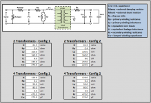
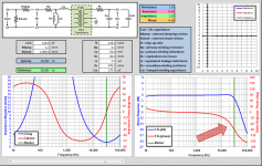
Attachment #5: Here is a table with all parameters for modeling the 2 and 4 transformer configurations with the spreadsheet I had posted here:
http://www.diyaudio.com/forums/plan...101-electronics-challenged-2.html#post2555863
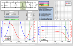
Attachment #6: For grins, here is a comparison of measured vs modeled response for the 4 Transformer Configuration 1 loaded with 220pF...a near perfect match 🙂
Attachment #7: For bengel’s ESLs, I would estimate the capacitive load will be equivalent to 120pF. Using Configuration 2 with a 1.1 ohm primary damping resistor, the -3dB bandwidth limit is > 30kHz.
Attachment #8: Repeat of Attachment #7 but including the 1.5uH output inductance of the Outlaw Audio amplifiers as part of the leakage inductance term.
http://www.diyaudio.com/forums/planars-exotics/286989-about-take-esl-plunge-16.html#post4658712
Attachments
-
 VTX_15VA_Toroids.png350.2 KB · Views: 368
 -
 VTX_Lprimary_core_saturation.png22.1 KB · Views: 364
 -
 VTX_Wiring_2Tgroups.png39.4 KB · Views: 364
 -
 VTX_Wiring_4Tgroups.png59 KB · Views: 189
 -
 VTX_parasitics_groups.png50.5 KB · Views: 185
 -
 VTXmodel_4T_Config1_220pF.png130.8 KB · Views: 182
 -
 VTXmodel_4T_Config2_120pF_damped.png125.7 KB · Views: 175
 -
 VTXmodel_4T_Config2_120pF_damped_AmpZ.png126.3 KB · Views: 161
Can you point me to a quote by Wright where he says this?...Mike Wright says output goes up as the square of the bias. But I seem to recall Bolserst doesn't agree.
All published ESL theory (Hunt, JansZen, Baxandall, Walker, etc) and experiments agree that acoustic output pressure increases directly proportional to bias voltage. Double bias voltage and you double output pressure (+6dB SPL).
Comparison of theory and measurements posted here:
http://www.diyaudio.com/forums/plan...m-resonance-change-hv-bias-2.html#post2378013
The negative stiffness force, which causes the diaphragm to by pulled toward one stator or the other when at rest, does vary with the square of the bias voltage.
http://www.diyaudio.com/forums/plan...rrent-vs-voltage-drive-esl-7.html#post2366501
Can you point me to a quote by Wright where he says this?
Did a quick check of manuals, texts... not found. If I were one of those British betting shops, I'd give really heavy odds that bolserst is right.
I suppose that if you take any instant in time and added together the electrostatic forces operating (the drive voltage and the bias) you'd like things linear. So, odd that the static displacement force operates on a square law.
Enthusiastic as I am about ESLs, there are moments when I wonder how you can get nice linear activation on a piece of SaranWrap tethered all around. Maybe I should take Hunt out of the library again.*
Ben
*I measure at least 50-60dB goodness (that's verging on .1% THD) with my ESLs and that includes a long chain of cheap gear and home heating noises** in the testing loop.
**don't ask to see proof until the home A/C season is over
Last edited:
Just want to, again, say thanks to bolserst for taking the time to test these. Hope others can use all of this wonderful info to build their ESLs.
Have question though, when you talk about the capacitive load, are you referring to each section or the entire panel? (I would presume entire panel). If so, the spreadsheet shows a 893.50 pF total and 89.35 pF section capacitance (my new config is a bit narrower 12.09 inches, and lost a section for 10 sections total - measure twice and cut once! 🙂 ).
Have question though, when you talk about the capacitive load, are you referring to each section or the entire panel? (I would presume entire panel). If so, the spreadsheet shows a 893.50 pF total and 89.35 pF section capacitance (my new config is a bit narrower 12.09 inches, and lost a section for 10 sections total - measure twice and cut once! 🙂 ).
The negative compliance force IS linear with displacement, just like an ideal spring.… I suppose that if you take any instant in time and added together the electrostatic forces operating (the drive voltage and the bias) you'd like things linear. So, odd that the static displacement force operates on a square law…
But the stiffness or spring constant is proportional to the square of the bias voltage.
If you plan to pick up a book to refresh yourself on the theory of ESL operation,
I would recommend the Baxandall’s chapter 3 in “Loudspeakers and Headphone Handbook”.
I find his derivations and discussion much easier to follow than Hunt.
https://books.google.com/books?id=T...ker and headphone negative compliance&f=false
Attachments
For an unsegmented panel, the capacitive load would simply be the capacitance of the entire panel. For segmented panels, the capacitive load has to be calculated based on the value of the segmentation resistors. Typically capacitive load for segmented panels is somewhere between capacitance of one segment or two segments…a definite benefit of segmentation.…when you talk about the capacitive load, are you referring to each section or the entire panel?
Imagine you used really really high resistance segmentation, it would make sense that the capacitive load would simply be the capacitance of the first segment. If really really low resistances were used, you are back to the entire panel capacitance. In the middle, you have to calculate with vector math or use SPICE simulation to determine the capacitive load, which will vary with frequency. Looking in the 10kHz – 40 kHz range will tell you what value to use for transformer response calculations when determining HF bandwidth limit. For your design, I calculated it would be around 120pF.
Bias Supply
Ok, rather than hijack another person's thread I thought I would just move this over there instead.
Basically, this is where I am at with my bias supply.
This: http://www.mouser.com/ProjectManager...sID=35096d16f4
+
This: New LM317 Adjustable Voltage Regulator Step Down Power Supply Module LED Meter | eBay (x2)
+
This: wall worts, current limiting resistors etc....
= 2 adjustable bias supplies capable of running up to 5 kV ????
I've adjusted the mouser project cart to use higher voltage components and lowered the capacitor values.
Just wondering what you might recommend for a resistor going into the ladder.... I was thinking something like 300 kOhm. If I understand all of this right, this is more for safety than anything since the current will ultimately be limited by the 20 MOhm resistor on the other end. i.e. I could touch the ladder at any point and not have a fatal amount of current go thru my body 🙂
I will probably add in the neon blinker circuit as well.
I am also curious if I could manipulate the display on those regulators to show me what the "calculated" bias voltage in kV would be..... i.e. add a voltage divider or something to the input to it.
I will draw this up in the new few days and post it.
Thanks again for all the help.
Value is not critical. Anything 100K to 1M would be fine.…what you might recommend for a resistor going into the ladder.... I was thinking something like 300 kOhm.
Should be as easy as that 🙂… could manipulate the display on those regulators to show me what the "calculated" bias voltage in kV would be..... i.e. add a voltage divider or something to the input to it.
I would also recommend adding some fixed resistors to the adjustment circuit so that you can’t accidentally turn the voltage level higher than the CCFL and/or caps and diodes can handle.
BTW, the link to your project manager doesn’t seem to work.
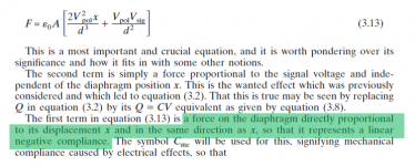
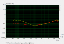
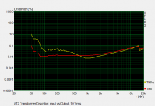
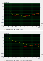
I forgot to include the distortion measurements for 5, 10, & 20Vrms.This post will be a summary of some tests I ran on 4 of bengel’s VTX transformers earlier this month...
In each plot, red curve was measured at amplifier output, yellow curve at stator connections.
Kinda hard to miss the point at which the core starts to saturate.
Other than that, pretty admirable distortion performance for the $.
Attachments
I would also recommend adding some fixed resistors to the adjustment circuit so that you can’t accidentally turn the voltage level higher than the CCFL and/or caps and diodes can handle.
I was thinking about that. I considering using a zener as a shunt to cap out the max voltage coming out of the regulator. Or just get a wall wort with a 6VAC output (gives me about 9V rectified).
BTW how much current will the CCFL thing pull? I would think it would be pretty small (read: I can use very small wall worts).
BTW, the link to your project manager doesn’t seem to work.
Fixed.... up'ped the voltage ratings. I am thinking about adding another step in the ladder and just limit the input voltage to the CCFL to make sure I don't go too high with the bias.
https://www.mouser.com/ProjectManager/ProjectDetail.aspx?AccessID=35096d16f4
Kinda hard to miss the point at which the core starts to saturate.
Other than that, pretty admirable distortion performance for the $.
Thanks for posting this, sets my mind at ease a bit. I believe I read long ago that anything below 1% is inaudible; and it's perception is based upon what frequency it is at - the lower the frequency, the harder it is to hear/detect. ..... so .1 % across the band I am using, is fantastic in my book.
I am just a little bit curious how these transformers stack up against purpose made expensive ones (for hybrid designs).
Hi,
they stack up frighteningly well.
In comparison to the Amplimo 1:50, two 120VA cores 230V/9V made no relevant difference within the intended working range feeding into my 1.2nF panel.
Due to higher primary inductance of the Amplimo the series resonance peak occured at lower frequency.
The maximum phaseshift reached -86°, just 3-4° worse.
The HF resonance was 2.5kHz higher at ~21kHz (which is excellent btw. for such a high capacitance load).
Amplitude response wise the difference was negligable.
Distortion figures were too low to make a difference and it was hard to put a figure to the measurement, as the measurement setup's own distortion (mainly the mic) were at least of similar order.
So the differences are rather impedance related than amplitude related.
Sonically I couldn't detect differences of relevance.
Due to the extreme electrical phase shift the choice of the amplifier is of much greater acoustic importance.
There are not many amps that deal with such a load unimpressed.
The majority of amps -regardless of fame and price tag- suffer and many simply suck.
Global feedback loops are almost a guarantee for sonic deterioration here.
Finding a matching amp can be come a long journey.
When ceramic and diamond equipped boxes are sonic microscopes then the ESL is the electron microscope, mercylessly revealing any so small flaw of the amplifier and associated components.
jauu
Calvin
The maximum phaseshift reached -86°
When ceramic and diamond equipped boxes are sonic microscopes then the ESL is the electron microscope, mercylessly revealing any so small flaw of the amplifier and associated components.
Right! Well said!
I'm still dreaming of producing ESL square waves that look good on an oscilloscope*. But with 86-degrees shifting around at some point in the needed bandwidth, it doesn't seem feasible.
Ben
*a buddy with Quads says his do it
This reminds me, I wanted to ask a question about the phase shift in the VTX transformers bolserst measured.
I see the phase starts diving down around 10K or so. 1st question is, is this absolute or relative phase and #2 if it is a problem, is there anything you can do to mitigate it? e.g. reverse the phase of the center segment?
I see the phase starts diving down around 10K or so. 1st question is, is this absolute or relative phase and #2 if it is a problem, is there anything you can do to mitigate it? e.g. reverse the phase of the center segment?
Hi,
don't mix up electrocal phase and acoustic phase. 😉
While the electrical phase shift can be quite severe, the acoustical is typically very linear, apart from the lower and upper band ends.
A1: the electrical phase shift is a absolute one, not corrected for delays like the acoustical (minimum phase).
A2: no, its not a problem. The issue could be solved with FIR filtering via a DSP.
All discussions about that showed a negligable sonic difference, rather more related to the added components in the signal path than a true acoustic effect.
jauu
Calvin
It depends, of course, on how much current you are pulling from it. In CCFL use, many modules can draw as much as 1A peak. Fortunately with properly operating ESL there is minimal current draw. Any wallwart capable of 300mA or more will work just fine for your application.…how much current will the CCFL thing pull? I would think it would be pretty small (read: I can use very small wall worts).
As Calvin already mentioned, purpose built transformers will have higher primary inductance and lower primary winding resistance. The higher primary inductance will result in an easier load on the amplifier, so lower distortion. The lower winding resistance will result in passing less of any core related current distortion on to the secondary.…I am just a little bit curious how these transformers stack up against purpose made expensive ones (for hybrid designs).
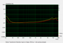
Both these items are reasons why building low distortion output transformers for tube amplifiers is so difficult. Generally the source impedance of the tube is similar in magnitude to that of the transformer input impedance, so any core related current distortion is passed straight on to the output. As an example of this, Attachment #1 compares the previously posted distortion for your VTX transformers @ 10Vrms with results for source impedance of 30 ohm. The take away from this is that as long as you have minimal resistance in the primary circuit of your transformer, it will add minimal distortion even if core is not of a low distortion type. (the only caveat being that the amplifier must be up to the task of gracefully supplying the required current)
Using the simple winding technique described in posts #102 and #105, distortion levels can be brought down to the point they are little different from that of the driving amplifier. Attachment #2 is an example of such a transformer designed to drive a segmented ESL and handle 50Vrms @ 80Hz with 140:1 step-up ratio using common M6 laminations.
Attachments
I assume you are talking about the phase shift from 0 to -180 at the upper bandwidth limit?I see the phase starts diving down around 10K or so. 1st question is, is this absolute or relative phase and #2 if it is a problem, is there anything you can do to mitigate it?
If so, the only way to correct it is extend the upper bandwidth limit, or use a digital filter to fix the phase. There is nothing unusual about ESLs in this regard. Pretty much every loudspeaker has a second order(or higher) LP behavior just above the audio band. They also pretty much all exhibit minimum phase behavior, so all have similar phase shifts in the top octaves. Extending the upper bandwidth to 100kHz and you would still have a 15 degree phase shift at 20kHz. If you see response measurement with flat phase response in the top octaves, usually a very small delay has been added(intentional or not) to the minimum phase response to achieve “prettier” looking plots. For example, if we added a 2.8mm delay to your VTX transformer response, we would have essentially flat phase response to 30Khz. (see dotted curve on plot)
Playing with the minimum phase extractor built in to the FRD blender(or just reading the tutorial and whitepaper) may be worthwhile if you are unfamiliar with how phase is directly tied to frequency response in minimum phase systems.
FRD Blender and Minimum Phase Extractor
At what frequencies are you interested in good looking square waves? Any of the segmented designs discussed in recent threads will pass square waves well up to about 1kHz. Stereophile published measurement of ESL-63 square wave response @ 1kHz (Quad ESL-63 loudspeaker Measurements | Stereophile.com). As you are probably aware, square waves are made up of an infinite series of in phase odd harmonics at falling levels. For decent “visual” representation of square waves you need at least the first 3 harmonics(3rd, 5th, 7th) with proper magnitude and phase. Surprisingly, phase rotation and falling level in harmonics above the 7th have minimal impact on the “look” of the square wave, although you will never achieve the near vertical leading and trailing edge slopes without them. For better square wave response above 1kHz, you need to extend the upper bandwidth limit of the entire audio chain well above 20kHz. If interested, see attached PDF for some details on frequency/phase content of square waves.…I'm still dreaming of producing ESL square waves that look good on an oscilloscope…a buddy with Quads says his do it
Attachments

Last edited:
- Home
- Loudspeakers
- Planars & Exotics
- About to take the ESL plunge