3pair output stage equals 6 source resistors.
Set the bias voltage low to start with, maybe 10.0mVdc across Rs1 and measuure all 6 after they have reached equilibrium.
Then increase in 10.0mV increments allowing time to resettle and re-measure.
By the time you get to 50mV (100mA) you have a table of measurements for all 6 Rs
You will see if they all remain very similar, or some wander off a little, or a lot. This will really show how well you selected for Vgs.
It was a test like this that showed how much better a thin mica is at transferring heat compared to a good quality low thermal resistance soft thermal washer. I had used my last three Thermal washers for all the upper devices and reverted to mica for the opposite side.
Hi AndrewT, thanks a lot for your advice again. So, it`s time to work, soon I gona say something.
Regards
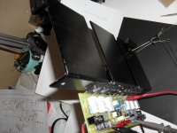
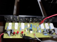
Hi AndrewT, the amplifier is working good the powers are more or less in balance the sound is charming, but I had to run a little beat because heat sink is only for test, is not enough. I put 47mV in S resistors because they are R47. Thanks for your suport and thanks to Mr. Mile also.
Regards and Pozdrav
Regards and Pozdrav
Attachments
Hi AndrewT, the amplifier is working good the powers are more or less in balance the sound is charming, but I had to run a little beat because heat sink is only for test, is not enough. I put 47mV in S resistors because they are R47. Thanks for your suport and thanks to Mr. Mile also.
Regards and Pozdrav
How hot do those tiny sinks get?
I Steel 🙂, in ten minutes I can have 40º celsius, more or less.How hot do those tiny sinks get?
Regards
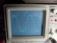
Hi Mr. Mile, I would like to hear something from you. I put 1Khz and 8R resistive load and I got this. The positive side almost clip and de negative side is as you can see in the photo (20V per divsion). I replace the drivers by 2SC4793 NPN positive side and 2SA1837 PNP negative side. Thanks in advance.
Pozdrav
Pozdrav
Attachments
Hi Mr. Mile, I would like to hear something from you. I put 1Khz and 8R resistive load and I got this. The positive side almost clip and de negative side is as you can see in the photo (20V per divsion). I replace the drivers by 2SC4793 NPN positive side and 2SA1837 PNP negative side. Thanks in advance.
Pozdrav
Bias circuit is in positive side and clip is unsimetrical... it is ok.
Regards
Bias circuit is in positive side and clip is unsimetrical... it is ok.
Regards
Thanks for your replay
Pozdrav
Hi. Mister Mile: my HV23 is working good but the Q3 A970 and Q6 C2240 are hot. Is this something bad? I send tension measure. Thank you
It is ok.
Regards
Q3 is showing Vbe as 1.3V and Q6 is showing 1.2V.Hi. Mister Mile: my HV23 is working good but the Q3 A970 and Q6 C2240 are hot. Is this something bad? I send tension measure. Thank you
Those are far too high.
Measure again.
Q3 is showing Vbe as 1.3V and Q6 is showing 1.2V.
Those are far too high.
Measure again.
Mister AndrewT. is right, this is the remeasured Vbe: Q3=0.51V. Q6=0.53V. R5=692mV(3.1mA) R14=663mV(3mA). Gracias.
I Mr. Mile, i have two questions to use FX100 PSU Protect with HV250. But i have some doubts about it, first: Which components are correct Electronic scheme 1 or Electronic scheme 2 ? Second, with +70 VDC -70 VDC should I change something.
Thanks in advance
Pozdrav
Thanks in advance
Pozdrav
Attachments
I Mr. Mile, i have two questions to use FX100 PSU Protect with HV250. But i have some doubts about it, first: Which components are correct Electronic scheme 1 or Electronic scheme 2 ? Second, with +70 VDC -70 VDC should I change something.
Thanks in advance
Pozdrav
With +/-70V use Diagram 2 without changes, only 10000uF/80V instead 10000uF/63V.
Pozdrav
With +/-70V use Diagram 2 without changes, only 10000uF/80V instead 10000uF/63V.
Pozdrav
Thanks for your quik replay
Pozdrav
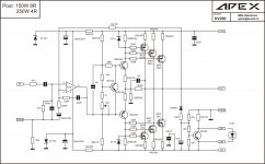
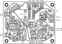
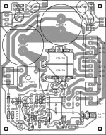
This is my contribution to APEX HV250 amplifier, for those without prejudices about OP amp in front. Thanks Mr. Mile
Pozdrav
Thank you for your contribution, nice pcb.
Pozdrav
The TL071 (and similar older FET opamps) will suffer from latch-up to the negative rail during clipping.
Even the lowly NE5532 sounds better, and does not latch-up.
I designed a commercial amplifier about 20 years ago similar to this with the TL072. The customer and I were auditioning it while being overdriven. He asked 'what is that horrible sound'. 'Latch-up' I replied. After substituting the NE5532 (with no other changes), the amp sounded much better at low volume levels, and did not latch-up when driven into clipping. We actually burned up a power transformer after driving into sustained clipping for over an hour. In the final design we ended up doubling the VA rating on the transformer.
Hi, for the F100 amplifier, is it possible to use a short circuit protect circuit. Like, as in apex PA protect circuit...The amp works very well for most applications and in a PA kind of situation, it needs a short circuit protection.
Last edited:
Hi, for the F100 amplifier, is it possible to use a short circuit protect circuit. Like, as in apex PA protect circuit...The amp works very well for most applications and in a PA kind of situation, it needs a short circuit protection.
Use PSU100 for F100 there is short circuit protect.
Regards
Attachments
- Home
- Amplifiers
- Solid State
- MOSFET Amplifier IRFP240/IRFP9240