Hello everyone!
I saw in one post Apex PSU 100 schematic running on 28V- 0-28Vca. I want to use with 33V-0-33Vca PSU100, paired with A33(those I have allready).Is this combination ok?
With this opportunity I would like to ask whether there is a tested PCB for A40 with final output transistors side mounted, not in line?
Thank you,
Laur.
Last edited:
Hi hv23 Rasakhtm but I could not I set
up in getting dc power
Post pictures, do you connect wire jumper on bottom side of pcb?
amp hv23
Hi all drain-source voltage MOSFETs 240 with the multi-train between 1 to 5.5
Goes up and down but side voltage MOSFETs 9240/7 v constant
Hi all drain-source voltage MOSFETs 240 with the multi-train between 1 to 5.5
Goes up and down but side voltage MOSFETs 9240/7 v constant
hv23
Hello Mr. apex Please tell me what already av400 circuit problem and I have the same problem
Hello Mr. apex Please tell me what already av400 circuit problem and I have the same problem
Hi guys, I have a few doubts regarding the circuit of F100.
1) The original schematic shows 2 pairs for a max power of 240 watts, but I have seen some boards in the bet with 3 pairs...Does 3 pairs give more output or is it not advisable ???...I mean are there any drawbacks like distortion apart from possible increase of power...
2) In the Atom 600, is it OK to add that much pairs of osfets without any problem.....
I am trying to experiment with the multiple pairs but just needed to clarify some doubts.....
There are three main factors affecting the maximum output power of a Power Amplifier.
a.) the installed Pmax of all the output devices in one channel. To3 can vary from 110W to 250W per device.
b.) the high voltage SOA. the DC Pmax can go up to only 15Vce upto 150Vce. Above that the SOA curve turns down and sometimes we see as little as 20% of Pmax @ 100Vce
c.) the load can vary from pure resistance to severe reactance.
Some would add heatsink cooling capability as a power output limit. In my view when using a Power Amplifier for domestic duty where average power delivered is -15dB to -20dB ref maximum, that Heatsink capability does not affect maximum power. Continuous long term testing does require a big sink, but that is more a test of the aluminium, rather than amplifier.
My guide for installed device numbers is given by:
maximum output power = sum Total Pmax and divide by Factor from 4 to 6
where that reduction Factor is ~4 for a mosFET output stage and 5 to 6 for BJT output stages.
Poorer SOA devices tend towards using reduction Factor of around 6 and the higher SOA devices use around 5.
BJT Power Amplifiers designed specifically for low ohms speaker can get slightly better than divide by 5. Maybe divide by 4.5
Last edited:
Mr Andrew: You could put an example to understand better. We are still learning from you. Thank you very much
"the installed Pmax of all the output devices in one channel. "
Assuming 100°C junction temp (heavy use), metal transistors rated to 200°C hold up better than plastic devices only rated to 150°C (some IRF devices are rated to 175°C).
At 100°C junction a 200W 200°C device will handle twice what a 200W 150°C device will.
If you choose plastic, I suggest you use (a lot) more devices.
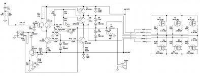
MOSFET Amplifier with Limiter
Awful way to draw a schematic, and a crude one at that...
Sorry for the offtopic...
?"the installed Pmax of all the output devices in one channel. "
Assuming 100°C junction temp (heavy use), metal transistors rated to 200°C hold up better than plastic devices only rated to 150°C (some IRF devices are rated to 175°C).
At 100°C junction a 200W 200°C device will handle twice what a 200W 150°C device will.
If you choose plastic, I suggest you use (a lot) more devices.
maximum power = (Tjmax - Tj) / (Tjmax - Taref)
for a 200W To3 rated at 200degreeC
(200-100) / (200-25) = 0.571, giving 0.571*200= 114W
(150-100) / (150-25) = 0.4, giving 0.4*200= 80W
Where's the "twice" factor?
And who runs with a Tj @ 100degrees C?
50degrees C to 70degrees C is more typical for the Tj in a power amplifier reproducing average levels around -20dB ref maximum power.
Last edited:
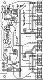
Simple mosfet amplifier pcb without limiter.
.. great, war machine...😀
- Home
- Amplifiers
- Solid State
- MOSFET Amplifier IRFP240/IRFP9240