Hi all,
I got two of these kits off ebay http://www.ebay.com
It all came very well packaged, and everything was there, except for a cap, which was the wrong value (220/63v instead of 150/80v). No big deal, i changed them all to 220/80v just for the heck of it. The PCBs look very robust and very well made, they're thick and heavy, almost glass like! They are, alone, totally worth the money. The output transistors (KEC D1047/B817) don't inspire a lot of confidence, but they should be ok for domestic music.
I assembled the kits and hooked them up to a 33v-0-33v beefy power supply for some testing. Both kits seem to work ok, and they sound just fine. I tried a 4Ω/100w sub woofer, and it quickly reached it's xmax. The heatsinks got warm after 2 minutes, but not hot...
Now the problem is, despite the good sound, i can measure no bias current at the outputs. The heatsinks are cold as beer even after an hour of being turned on with no signal at the input. I used 10Ω power resistors at each rail, and i calculated an idle current of about 13-14mA per rail, per amp module. It seems very low😕.
With inputs shorted, the emitter resistors (0.15Ω) all measure dead zero mV (0.0). The voltage across R26(200Ω) is about 850mV. I think thats about half the optimal voltage to even begin conduction at the output transistors.
What baffles me, is that the amp sounds just right with no apparent output bias. Even the top end sounds smooth, no signs of being grainy or harsh at all. Is that normal?
Could it be that the rail voltage is rather low? The optimal voltage per rail, according to the designer, is around 65v. I will test again with the power supply which i intend to use permanently (57v rails). I hope the higher dc voltage will affect the, almost non existing, standing current.
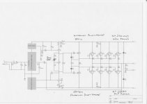
Here is a (not very revealing) schematic i lifted from another thread. I haven't checked for errors, but it seems close enough.
I got two of these kits off ebay http://www.ebay.com
It all came very well packaged, and everything was there, except for a cap, which was the wrong value (220/63v instead of 150/80v). No big deal, i changed them all to 220/80v just for the heck of it. The PCBs look very robust and very well made, they're thick and heavy, almost glass like! They are, alone, totally worth the money. The output transistors (KEC D1047/B817) don't inspire a lot of confidence, but they should be ok for domestic music.
I assembled the kits and hooked them up to a 33v-0-33v beefy power supply for some testing. Both kits seem to work ok, and they sound just fine. I tried a 4Ω/100w sub woofer, and it quickly reached it's xmax. The heatsinks got warm after 2 minutes, but not hot...
Now the problem is, despite the good sound, i can measure no bias current at the outputs. The heatsinks are cold as beer even after an hour of being turned on with no signal at the input. I used 10Ω power resistors at each rail, and i calculated an idle current of about 13-14mA per rail, per amp module. It seems very low😕.
With inputs shorted, the emitter resistors (0.15Ω) all measure dead zero mV (0.0). The voltage across R26(200Ω) is about 850mV. I think thats about half the optimal voltage to even begin conduction at the output transistors.
What baffles me, is that the amp sounds just right with no apparent output bias. Even the top end sounds smooth, no signs of being grainy or harsh at all. Is that normal?
Could it be that the rail voltage is rather low? The optimal voltage per rail, according to the designer, is around 65v. I will test again with the power supply which i intend to use permanently (57v rails). I hope the higher dc voltage will affect the, almost non existing, standing current.
Here is a (not very revealing) schematic i lifted from another thread. I haven't checked for errors, but it seems close enough.
Attachments
It sounds strange a bit. You should hear the result of the missing bias, especially with low level music.
If You want to set the bias, just replace the 1k resistor in the Vbe multiplier with 2kohm multiturn trimmer. That way is better, and safe comparing to the solution, mentioned on the schematic. Allways start from the maximum resistance, and reduce it carefully!
Sajti
If You want to set the bias, just replace the 1k resistor in the Vbe multiplier with 2kohm multiturn trimmer. That way is better, and safe comparing to the solution, mentioned on the schematic. Allways start from the maximum resistance, and reduce it carefully!
Sajti
Thanks Sajti,
that's nice to know. As i understand it, it's safer to put a trimpot in place of the 1k resistor, because if the trimpot, for whatever reason, gets open circuit even briefly, it will not send the bias current through the roof. I'm thinking about a 100k or 50k linear trimmer, parallel to the existing 1k resistor.
But first, i will check the bias with the higher rails (+-57v), and if no current appears, i will then start with the mods. I think about 10mA per pair, ought to be enough.
Hi Filthyone,
Good advice from Sajti - having the trimmer on the emitter side is definitely much safer.
A would run this kind of output stage at 60-70mA of quiescent current per pair. It will run rather warm, but ensure the low crossover distortion throughout the whole audio bandwidth.
Rails voltage is not going to really influence the bias, unless your VAS idle current will noticeably increase with higher rails, which should not be the case in a well-designed front-end.
Cheers,
Valery

Hi Valery and thanks for the reply.
70mA of QC per pair? Isn't that really high? That should equate (if i am correct) to about 4 Watts of heat per transistor on 57v rails, times 8 for each channel = 32 watts per channel dissipated as heat, all the time. Isn't that unnecessarily stressful?
I don't mean to be rude, i am sure you have/there are reasons, which is why i ask.
I guess this question has been answered all over this forum, but what's the real benefit of having a high bias current in class AB, instead of just the bare minimum to ensure no crossover distortion??
Hi Valery and thanks for the reply.
70mA of QC per pair? Isn't that really high? That should equate (if i am correct) to about 4 Watts of heat per transistor on 57v rails, times 8 for each channel = 32 watts per channel dissipated as heat, all the time. Isn't that unnecessarily stressful?
I don't mean to be rude, i am sure you have/there are reasons, which is why i ask.
I guess this question has been answered all over this forum, but what's the real benefit of having a high bias current in class AB, instead of just the bare minimum to ensure no crossover distortion??
Hi Filthyone,
Bob Cordell explains the biasing principles in his "Designing Audio Power Amplifiers" book. Skipping all the theory behind it, the key principle for setting the optimal bias for emitter-follower type of output stage is that the voltage drop across the emitter resistor has to be approximately 26mV for each of the output resistors.
With 0.22R emitter resistors, corresponding quiescent current comes to 118mA per output pair. My practical experience shows that depending on particular design, 60-90 mA per pair is enough for suppressing crossover distortion to acceptable level.
10-15mA per pair would be enough for CFP output stage, but this is not the case in the amplifier we're talking about.
Cheers,
Valery
I design my own amps so have no setup procedure.
So I decided to apply a sine wave and monitor the output.
I turn up the bias until crossover distortion just goes.
Seems to be fine.
Why have more bias than you need ?
Its just wasted in heat.
So I decided to apply a sine wave and monitor the output.
I turn up the bias until crossover distortion just goes.
Seems to be fine.
Why have more bias than you need ?
Its just wasted in heat.
Need is the issue. If you are talking of PA systems, where the expected use is at high power and SPL continuously, the remaining crossover distortion goes unnoticed. However in home Hi-fi, which is often playing below 1 watt RMS, that amount of crossover distortion becomes more obvious and unacceptable to home listeners, or at least those I talk to......Why have more bias than you need ?.....
The optimum bias for Hi-fi is the lowest possible crossover distortion, whether that should be a 26 mV drop across the emitter resistors of a class AB EF output stage or, as Valery pointed out, somewhat less according to the performance of the circuit and devices used. That's one good reason not to use PA sized amplifiers in your home 😉
I design my own amps so have no setup procedure.
So I decided to apply a sine wave and monitor the output.
I turn up the bias until crossover distortion just goes.
Seems to be fine.
Why have more bias than you need ?
Its just wasted in heat.
Right, as Ian just pointed out - depends on your need 😉
Nigel, how do you see it just goes? If it becomes invisible on the oscolloscope, it still does not mean it's gone. THD can still be at the level of, say, 1%, even if the sine wave looks perfectly clean on the screen.
If you use a high-presision THD meter or a spectrum analyser, you can see the real level and harmonic profile of the distortion. Now you can find the bias value, giving you either the lowest distortion, or a good compromise between distortion level and heat dissipation. It may be different, depending on particular design. So, manufacturer specifies the bias value for each particular amplifier in the service manual.
And then, procedure for the user is simple - connect DMM to the emitter resistors (source resistors in case of MOSFETs) and set the voltage drop to recommended value.
For 0.22R resistor and BJT output stage it will most likely be in the range of 13...26mV.
Well, as i suspected, this is an, yet another, ambiguous subject.😀
I myself tend to lean more on the "absolutely lowest necessary" side of the argument. But i can see why someone would go higher to achieve near-zero distortion and ensure HiFi standards. Yet another compromise, like everything in electronics, and almost everywhere.🙄
What baffles me, is that i can't hear any crossover distortion on an amp with practically zero bias. I don't have a well trained ear, but i know the sound of crossover distortion pretty well.
I don't have an oscilloscope, but i will experiment with different settings (none/low/high) at a low volume, and see if i can hear a difference. I know this is not very scientific, but then again, my ears are the ones i want to please. So they are the ultimate judge.
Well, as i suspected, this is an, yet another, ambiguous subject.😀
I myself tend to lean more on the "absolutely lowest necessary" side of the argument. But i can see why someone would go higher to achieve near-zero distortion and ensure HiFi standards. Yet another compromise, like everything in electronics, and almost everywhere.🙄
What baffles me, is that i can't hear any crossover distortion on an amp with practically zero bias. I don't have a well trained ear, but i know the sound of crossover distortion pretty well.
I don't have an oscilloscope, but i will experiment with different settings (none/low/high) at a low volume, and see if i can hear a difference. I know this is not very scientific, but then again, my ears are the ones i want to please. So they are the ultimate judge.
Experiments must be well-prepared. Ears are good instruments, but they can full you easily 😉 The best way for comparisons is a proper organized blind A/B test. 2 channels with different bias settings and ability to switch them instantly. Somebody else should switch them, so that you don't know which one is playing. You may be surprise with the results. Difference in sounding with distortion levels of 0.3...0.5% THD and 0.03...0.05% THD is normally clearly recognizable. If the signal source and speakers are up to the right level in terms of distortion - this is the other important point 😉
That is actually a really nice idea!
I will have my bro switch between two channels with different bias levels, one at a time (but with the same, mono input signal), and while i won't be looking, i will try and make a fool of myself.😱
God i love experiments, even "half assed" ones like this!
I will have my bro switch between two channels with different bias levels, one at a time (but with the same, mono input signal), and while i won't be looking, i will try and make a fool of myself.😱
God i love experiments, even "half assed" ones like this!
Now i've got another question,
i am thinking of putting 10Amp fuses on the PS board, between the filter caps and amp pcbs, just to prevent the fireworks in case something goes horribly wrong. Is this ok? What if only one of the rails gets open circuit? Will that cause any damage?
i am thinking of putting 10Amp fuses on the PS board, between the filter caps and amp pcbs, just to prevent the fireworks in case something goes horribly wrong. Is this ok? What if only one of the rails gets open circuit? Will that cause any damage?
Good question. One rail down will cause significant DC offset at the output, most likely killing the woofer, unless protection board disconnects the speaker and shuts down the amp. Advanced protection boards can instantly disconnect the rails symmetrically in case of trouble.
For example, see 21-st century control board, following the link in my signature.
For example, see 21-st century control board, following the link in my signature.
Back to the build,
I modified the circuitry by adding a 50k 25turn pot across the 1k BE resistor of the Vbe multiplier (Q8), so i could fine tune the bias current. It works great, and i tried a lot of different values but settled at about 20mA per output pair.
While comparing with the other channel, which had zero output bias, I COULDN'T tell them apart, they sounded exactly the same to me (with soft music as a source). But when i tried with a pure 1kHz sine wave, i thing there was a slight raspiness in the no bias channel, but nothing too obvious. Anyway, seems some bias helps, and the amps sound fantastic, running off 60 Volt rails.
Now the problem is that the bias is very dependent on the heatsink temperature. When i start the amp up (cold heatsinks), the bias current is where it is supposed to be, exactly where i set it, at about 20mA per pair. As the heatsinks slowly warm up (without input signal), the bias settles at around 5mA per pair. If i play some music for a while and the heatsinks get real hot (to the point of no touchy), the bias almost disappears (about 1ma per pair). As the heatsinks slowly return to just warm, the 5mA bias also returns! Go figure....
Is this normal? I have checked everything, all output transistor are firmly attached to the heatsink, and are warming up at the same rate, including the bias control transistor (Q8). Shouldn't the bias be more stable? Am i missing something?
Please, give me some light. Is the bias supposed to be setup when the amp is idling or when it is real hot. Does this behavior indicate a problem with my thermal feedback?
Attachments

1)Power on the amplifier.
2)Adjust the bias.
3)leave the amplifier for warming without any signal to inp, no load at the output.
3)Adjust the bias again for the same value.
Check the tempereture on the heatsink ! This must be a little warm,not hot.If it is hot a bigger one is needed,or a lower bias.
Now connect the inp and out ,play music,as the temperature raise (heatsink realy hot) bias decreases. This is normal.
Hi guys, quick question to the experienced:
I am building the attached DC protection circuit, which i found on the internets. It works great (in simulation).
Now, is it OK to use a single pole relay to switch the common negative (ground) of the speaker outputs, instead of the actual outputs? The reason being that i have at hand a nice, high current, quality, Omron relay, which is single pole, and i don't want to use a crusty little double pole (or buy an expensive one🙂).
I don't see a reason why not, but am asking in case i am missing something...
Thanks for any input!
Attachments
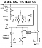
Switching the Return from the speakers is almost as effective. This works for over driving and for DC protection. It's done this way in the My-Ref amplifiers.
Where it is not good is if there is an accidental short from Speaker Out/Flow to any grounded metalwork.
I don't like your detect and trigger circuit. Find a better one.
Where it is not good is if there is an accidental short from Speaker Out/Flow to any grounded metalwork.
I don't like your detect and trigger circuit. Find a better one.
Thanks AndrewT, thats nice to know.
What's wrong with the above circuit? As tested in simulation, it works very well as It kills the relay instantly (within few milliseconds) at the presence of any rail level DC. Only problem is that it can trigger with very low frequency/high amplitude signals, like 5hz at 30Vrms. Some may find that a feature, including me!🙂
OK, now that i think about it, a relay oscillating back and forth on that kind of output voltage levels can destroy lots of stuff, including tweeters and of course itself (contacts)!!
Can you recommend a better solution, but equally simple to be built on a perfboard? Please no micro controllers, only analog stuff (the good stuff)
Last edited:
- Home
- Amplifiers
- Solid State
- LJM L20 V9.0 Amplifier