Sadly I had lost track of their development. 😱...and if you want to push them to "99%" use devices like the Klippel "Controlled Sound" processing.
Thanks for the reminder!
…So what is the point of manipulating t/s with MF? It's simply not necessary.
As KSTR and others have mentioned, the ability to manipulate T/S parameters with MFB has benefits in stability of performance compared to simple EQ. As far as flattening the response, you can think of MFB as an adaptive EQ, making the final response less influenced by variations in the mechanical/acoustical parameters of the woofer and/or enclosure. Additionally, the compliance and damping of the MFB modified T/S parameters will be more stable and moderately more linear with excursion. From an OEM standpoint, it would allow stocking and using a single woofer for several different box sizes and designs. These advantages may not be seen as particularly important for one-off DIY projects.…If you want to use MF as a glorified eq...
Hmmm…I hadn’t noticed any disparaging comments concerning theory or modeling techniques over in the Planar Forum. Most modeling tools have a firm foundation in theory, but do have limitation when it comes to predicting large signal behavior. Perhaps that is the bone of contention? (It's a small bone since most users try to avoid using woofers beyond their linear range, but certainly valid)Ben doesn't like simulators, doesn't understand what they do or what they are for, and mocks people that use them.
@ Bentoronto,
Can you state specifically your feelings on modeling techniques for dynamic drivers and when/if you feel they are useful? Probably best to avoid names of specific users or modeling programs and stick to the techniques and what you consider their valid design space. This should improve understanding when others read or respond to your posts.
Well since you ask, you do need to plan before building but given the rough accuracy of speaker models, I'd only say, "everything that is worth knowing about enclosures, you can do on the back of an old envelope or otherwise estimate from prior knowledge. And if you don't know enough about enclosure design to do that, you have no business blindly swallowing the verdict of a sim either".@ Bentoronto,
Can you state specifically your feelings on modeling techniques for dynamic drivers and when/if you feel they are useful?
Ben
Last edited:
As KSTR and others have mentioned, the ability to manipulate T/S parameters with MFB has benefits in stability of performance compared to simple EQ. As far as flattening the response, you can think of MFB as an adaptive EQ, making the final response less influenced by variations in the mechanical/acoustical parameters of the woofer and/or enclosure. Additionally, the compliance and damping of the MFB modified T/S parameters will be more stable and moderately more linear with excursion. From an OEM standpoint, it would allow stocking and using a single woofer for several different box sizes and designs. These advantages may not be seen as particularly important for one-off DIY projects.
While I don't disagree with anything here, you know my standpoint. There are better ways to achieve all the benefits that MF can provide at least for the DIY'er.
Hmmm…I hadn’t noticed any disparaging comments concerning theory or modeling techniques over in the Planar Forum. Most modeling tools have a firm foundation in theory, but do have limitation when it comes to predicting large signal behavior. Perhaps that is the bone of contention? (It's a small bone since most users try to avoid using woofers beyond their linear range, but certainly valid)
@ Bentoronto,
Can you state specifically your feelings on modeling techniques for dynamic drivers and when/if you feel they are useful? Probably best to avoid names of specific users or modeling programs and stick to the techniques and what you consider their valid design space. This should improve understanding when others read or respond to your posts.
It will likely be very hard to get a straight answer to this from the horse's mouth but a quick search of his username with the keyword "sim" (or variants like "sim lovers" or "sim believers") will give days of answers. This thread in particular is a goldmine. http://www.diyaudio.com/forums/subwoofers/290986-impedance-chart-need-explanation.html
With examples like this:
+1. Quite a well-spoken criticism of the "religious beliefs" (and shibboleths) of the local wannabes-engineer sim-friendly crowd. Umm, good thing you didn't get into more alienation by diss'ing "tapped horns" - criticism of TH is not tolerated at DIYaudio.
But given sumaudioguy's and Planet 10's critique, the most sensible reaction would be to abandon unjustified faith in trick "higher-order" boxes that depend on assumptions about assumptions to work right?
While the elements of the Olson/Beranek model still determine the sound of a given driver, there is only one design decision for sealed boxes (and comparably for open boxes). That is, how big a box do I need for that driver to keep from shifting my resonance beyond what I can live with?
Overall, a great misplacement of effort to fuss about boxes - and really laughable when folks dream of miraculous benefits from sixth-order complex constructions. As far as I'm concerned (and since starting to research it long ago), if you really care about quality bass sound (and know which is the hot end of a soldering iron), the path forward is motional feedback.
Question for sumaudioguy: what causes the divergence of the two markers of resonance. Shouldn't they be the same (at least in free-air), like we always thought?
Ben
This covers most of Ben's main dogma points.
1. Evils of resonance.
2. Validity of sims (and mocking people that use them).
3. Superiority of motional feedback.
But where's #4, the horrid behavior of the moving coil driver? Oh wait, that's in the next post.
While challenging to measure let alone to standardize, I think we need to know how primitive Rice-Kellogg drivers work at say, 40 dB below regular home listening levels ...
At those levels, I bet it turns out Rice-Kellogg drivers have some kinds of unlinear suspension flaws akin to stiction or tin-can-top (I forget the name) or accordination (I made that up) that isn't in the T/S model.
More from the same thread -
Recent posters sound like medieval monks arguing about insubstantial concepts. What I want to know is WHAT physical aspect of the shaking-cardboard driver isn't behaving nicely. With that information, the hardware folks can get to work addressing the problem. Beats me why anybody in the world would think some stiff fabric and a roll of rubber makes a perfect spring.
Maybe a couple of extra fudge-factors could be added to today's favourite model, like Einstein did once (in error). Even guesses are welcome.
(For sure, arguing that luckily errors counter-balance is a kind of going-to-ground logic that leads nowhere except lets sim advocates with no curiosity sleep better at night.)
Ben
There are literally hundreds of similar posts if you do a search, all covering the same 4 themes.
There's also the small detail that he doesn't know how sealed boxes work. He regularly demands to know why simulators "command" people to make sealed boxes so small, despite being told simulators only calculate what they are told. He advocates large sealed boxes (the only parameter being how large you can live with), which in itself isn't a bad perspective, but he believes all drivers in these large sealed boxes will have a high qtc spike in response at the low knee, which he finds subjectively pleasing (but only occurs with very high qts drivers in large sealed boxes).
These naive misconceptions and poor understanding of the concepts involved have prompted recurring discussions for the past few years. No matter what evidence is provided nothing ever changes.
Last edited:
That's ridiculous to say of any alignment other than a sealed box.everything that is worth knowing about enclosures, you can do on the back of an old envelope or otherwise estimate from prior knowledge. And if you don't know enough about enclosure design to do that, you have no business blindly swallowing the verdict of a sim either
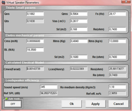
forr rightly mentioned 😉the brilliant Erik Stahl, who invented & patented the AceBass system OVER 30 years ago ! For those that aren't aware of him, or what AB accomplished, it's able to manipulate/alter the real T/S of a driver/s by synthesizing them in real time. So you can design a box/driver/system that more suits your desires etc, with a driver that initially had different properties = Brilliant 🙂
From IPAL's Pdf
IPAL has a version of AB included in its software. They call it VIRTUAL SPEAKER MODELING
DPC
@ esgigt
It's NOT time-travel, but time manipulation, & it's used Very effectively in Lots of Pro software !
From IPAL's Pdf
Like to see you Try & design for eg, a tapped horn that way
From IPAL's Pdf
4. REFERENCES
[1] Karl Erik Stahl - “Synthesis of Loudspeaker
Mechanical Parameters by Electrical Means: A new
Method for Controlling Low-Frequency
Loudspeaker Behavior” – AES Journal, Vol. 29,
September 1981
IPAL has a version of AB included in its software. They call it VIRTUAL SPEAKER MODELING
DPC
@ esgigt
It's NOT time-travel, but time manipulation, & it's used Very effectively in Lots of Pro software !
From IPAL's Pdf
“ZERO LATENCY” DSP
An innovative architecture that ensures an astonishing 10us (microseconds) latency on the critical feedback paths allows “analog type” feedback approach with the ?exibility of a DSP core.
Originally Posted by Bentoronto
"everything that is worth knowing about enclosures, you can do on the back of an old envelope or otherwise estimate from prior knowledge.
Like to see you Try & design for eg, a tapped horn that way
Attachments

Well since you ask, you do need to plan before building but given the rough accuracy of speaker models, I'd only say, "everything that is worth knowing about enclosures, you can do on the back of an old envelope or otherwise estimate from prior knowledge. And if you don't know enough about enclosure design to do that, you have no business blindly swallowing the verdict of a sim either".
Ben
One more comment on this ridiculousness - this is the recent measurement of a front loaded horn overlaid on top of the design sim.
How's that for "rough accuracy of speaker models" and "unjustified faith in trick "higher-order" boxes that depend on assumptions about assumptions to work"?
That's the Submaximus V3 designed by LTD02 and built and measured by asarose.
And it uses the Mach 5 UXL, a large coil driver with lossy inductance issues that doesn't sim accurately unless adjusted for. I'm not sure if LTD02 used my exact adjustment method but he is well aware of the issue (he was a major contributor to my research after all), he did adjust for it, and his sim is virtually identical to a sim adjusted by using the "Large Coil" checkbox in Hornresp. This is the first horn I'm aware of that was designed using my research. His comments on the matter are -
the model has the motor detuned significantly because of the inductance effects (and the cab was modified from the original for that reason). the driver may not need quite that much detuning, but it shows that the horn will have a great response even if the inductance effect significantly limit the effective motor strength. de-tuning the motor of high inductance drivers for horns was given an extensive treatment in a paper by diyspeakerguy. a search should pull up his post and the paper that several of us contributed to on the topic. bottom line, i think that we have a pretty close model here. my guess is that room effects are going to have a much greater impact than the margin of error in the model at this point.
Looks like all those assumptions about assumptions in the sim worked pretty well. Also looks like my empirical research on adjusting Bl to compensate for lossy inductance worked pretty well too.
Lots of info on this flh in this post if anyone is interested - Gjhallerhorn v2 or Submaximus for pair of Uxl's - Page 3 - AVS Forum | Home Theater Discussions And Reviews
Last edited:
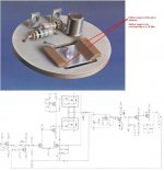
Indeed the best option is to mount the sensors during manufacturing. But have you ever seen such a Philips unit on the inside
Simple but age affected.
The compliant coupling of the piezo sensor (see attachment)hardens with time, altering the feedback behaviour.
(Philips and Peerless used the same 8” and 12” MFD Philips drivers with this sensor on their MFD loudspeakers).
The T/S parameters can't be considered alone, they always belong to a closed circuit. And it is the behaviour of the whole circuit which determines the transfer function. Erik Stahl made a brilliant demonstration of this.
Loudspeaker lower bass response using negative resistance and impedance loading
A more recent advanced plan (in theory) for cone control, DSP heavy
Position detection of an actuator using impedance
George
Attachments
Simple but age affected. The compliant coupling of the piezo sensor (see attachment)hardens with time, altering the feedback behaviour. (Philips and Peerless used the same 8” and 12” MFD Philips drivers with this sensor on their MFD loudspeakers).
Some time ago, I had the smallest of the MFB Philips loudspeakers in hands.
It should have been more than thirty five years old. All specs were as intended and there was no need to touch to any of the adjustable pots. So the compliant of the piezo sensor seems to have not much suffered but I could not tell more.
Components were standard but the general construction was impressive, made to last.
I suspect that the piezo sensor, small and light, and its compliant coupling is the reason why Philips got far better results than those obtained by diyers gluing an accelerometer available on the market to the voice coil or the cone.
Last edited:
A more recent advanced plan (in theory) for cone control, DSP heavy
Position detection of an actuator using impedance
As best as I can read (and understand) the black-and-white print, Fig. 19 suggests that things go bad with a delay somewhere between 10 and 50 microseconds, with a signal around 3000 Hz. I guess it also depends on your upper pass freq.
Can somebody explain that chart, please. What is their "correction"?
B.
Last edited:
Ben,As best as I can read (and understand) the black-and-white print, Fig. 19 suggests that things go bad with a delay somewhere between 10 and 50 microseconds, with a signal around 3000 Hz. I guess it also depends on your upper pass freq.
Can somebody explain that chart, please. What is their "correction"?
B.
I'm not following what you mean by "things go bad with a delay somewhere between 10 and 50 microseconds, with a signal around 3000 Hz".
As far as I can tell without an explanation of the acronyms used, figure 19 shows the induced phase between speaker current and voltage induced by Back Electrical Motional Feedback.
Although the induced phase between speaker current and voltage is somewhat related to the output phase of a loudspeaker, using FIR (Finite Impulse Response) filters, (almost) any loudspeaker's phase and impulse response can be made to be flat, that is 0 degree phase shift through the entire audio range.
It occurs to me that since you already own DSP capable of implementing FIR filters, what one of your primary goals you desire (flat phase response through the entire audio range) using MF to accomplish can be done for free. FIR filters going down to a few Hz do impart a fair bit of latency, if you want video to sync to the FIR delayed audio, you would have to also delay it by the same amount.
http://www.diyaudio.com/forums/mult...ker-phase-linearization-eq-fir-filtering-tool
The latency in FIR filters is dependent on the lowest frequency you decide to have flat phase too (the lower the flat phase response, the longer the delay required, a multiple of the wavelength time duration) , if you decide on 20 Hz as the low limit for flat phase, the audio lagging behind the video (as it does in the back of a movie theater) may not be too objectionable.
As far as reduced distortion, as has been pointed out many times before, simply using speakers with adequate displacement capability for the desired SPL can keep distortion to inaudible % levels.
By the way, in listening tests I have found I'm fairly sensitive to LF distortion (well above the statistical norm) but am rather insensitive to LF phase "wrap".
Listening to recordings with various amounts of phase shift on Sony MDR-7506 headphones, (kind of an "industry standard" due to high sensitivity, clean high SPL capability, and near-flat frequency and phase) I found I could not tell the difference in A/B testing between a music recording with no phase shift and the same recording with thousands of degrees of phase shift spread over a ten decade frequency range, multiple 360 degree phase "wraps" .
For that reason, even though I shelled out over $1000 to buy a DSP capable of implementing FIR filters, I have have lost the motivation to do the work involved in learning the programs needed to accomplish the implementation.
I am still motivated to build lower distortion sub-woofers for both my home theater and live sound systems, and have finished my shop sub-woofer.
Cheers,
Art
Last edited:
For me, it's exactly the opposite. I can easily tolerate gross distortion in the LF range provided it does't spoil the lower midrange (like when it's a two-way with lots of resulting IMD in the midrange), but image depth and clarity (I'm a soundstage junky) as well as the impact of LF transients (like kick drum and plucked strings of an upright bass) suffer a lot when too much phase wrap is present. Therefore I'm using FIR phase unwrapping, not only of the crossover allpass behavior but more importantly also of the intrinsic (minimum phase) phase wrap of the LF roll-off. Notably on smaller speakers with 50Hz-ish corner freq, while with system having very low cutoff there's much less of the "blurred transient problem" for me.By the way, in listening tests I have found I'm fairly sensitive to LF distortion (well above the statistical norm) but am rather insensitive to LF phase "wrap".
Might have to do with me being an active musician playing drums, guitar and bass since my early childhood.
KSTR,For me, it's exactly the opposite. I can easily tolerate gross distortion in the LF range provided it does't spoil the lower midrange (like when it's a two-way with lots of resulting IMD in the midrange), but image depth and clarity (I'm a soundstage junky) as well as the impact of LF transients (like kick drum and plucked strings of an upright bass) suffer a lot when too much phase wrap is present. Therefore I'm using FIR phase unwrapping, not only of the crossover allpass behavior but more importantly also of the intrinsic (minimum phase) phase wrap of the LF roll-off. Notably on smaller speakers with 50Hz-ish corner freq, while with system having very low cutoff there's much less of the "blurred transient problem" for me.
Might have to do with me being an active musician playing drums, guitar and bass since my early childhood.
Hearing perception is an interesting subject.
Even though I am insensitive to phase wrapping, I have no doubt that others are.
I also have played multiple instruments (poorly) since I was young, and have been actively involved in mixing live bands and recording since 1971. I have been told that I'm quite good at mixing, and many of the recordings have stood the test of time quite well, proving a good recording is a good recording regardless of what medium was used to make it. I have live cassette recordings from the 1970s- through the 1990s that I transferred to CD format, then to iTunes, my aging ears can't tell the difference between the different digital formats unless I A/B them, though the analog tape sound does lend a bit of a "warmth" to them. I have been recording using various digital formats since 1995.
Although phase wrapping does not seem to change my perception of the kick drum punch or plucked strings (of any instrument) I am sensitive to poor phase transitions. I have built literally every kind of bass enclosures, and have found that the only type I could not tolerate were band-pass types, their rapid phase change at the band pass makes it impossible to get a smooth phase transition in the crossover region using standard "old school" filters, unless crossed well below the band pass point. Perhaps using FIR filters on band-pass cabinets could "cure" them, but there is some truth to the old saying "you can't polish a turd".
One more point that may explain my phase "insensitivity"- as I mentioned before, I use Sony MDR-7506 in the studio, and GK-Ultraphones for live use. The GK Ultraphones uses the same MDR-7506 mounted in Peltor ear muffs, providing up to 30 dB of isolation, critical for PFL (pre-fade listen) "fine tuning" of tone controls for voice and instruments "on the go" when no time for sound check has been allowed.
Since I have been using 24 dB LR crossovers in three and four way systems for the last 35 years (12 and 18 dB prior to that) I have rapidly been switching between the flat phase of the phones to the 1080 degree (at minimum) wrap of a four way crossover, or throughout the last 20 years, mostly the 720 degrees of a 3-way. I always equalize the live sound systems to sound as much like the phones as possible, other than room ambience. Most of my live mixing this century has been outdoors, with a roughly equal split between acoustic Jazz, and a variety of everything else from hip-hop, country, rock, and death metal, if I can't avoid it.
So I am listening to three different "phases" of the music on each gig- the acoustic or musical instrument amplified sound, the sound of the PA speaker system, and the sound altered in phase by the microphones- condenser and dynamic mics each have differing amounts of phase lag, so any recording or reinforced sound has their phase "imprint", and the mixed phase of multiple mics and tone controls already imparted to it.
So although I don't question your ability to hear phase differences, do understand that each and every recording contains phase alterations from the original signal, unless recorded mono in an anechoic chamber using FIR filters.
Of interest, although FIR equalization is available in the digital medium, most recording engineers still prefer to use the "old school" filters that give the classic sound we grew up listening to- "phase wrapped" music.
Cheers,
Art
I think you are sensitive to the Group-Delay present at the low freqs.
Isn't "group delay" a euphemism used for BOOM by people who build bass reflex enclosures? Others say, "boom".
B.
Ben,Isn't "group delay" a euphemism used for BOOM by people who build bass reflex enclosures? Others say, "boom".
One of the "boomiest" subs I can think of is the Cerwin Vega B-36, a folded horn.
Other examples include 6th order band-pass, like the tiny BOSE "sub-woofers".
"Boom" is a descriptor for a narrow peak (AKA "Johnny one note) in the bass region, which can occur in any (boomy) design, or many rooms.
I have mixed in far too many "boom boom rooms" designed to make audience noise seem even louder than it already is.
Group delay is inherent in any bass speaker not corrected with FIR filters.
Do you actually have any interest in correcting the phase response of your sub-woofers, or is your current "work" on MF just more hand waving ;^) ?
Art
Last edited:
Isn't "group delay" a euphemism used for BOOM by people who build bass reflex enclosures? Others say, "boom".
B.
I don't think so but it's often impossible to infer what people actually mean when they use words incorrectly.
The correct definition of group delay is absolutely not a euphemism for "boom". If you look at a group delay graph you can see exactly what it is - certain frequencies are delayed by a given amount of time. This is time smearing, not boom. Fixing the group delay would not subjectively sound "less boomy", rather "tighter" or "faster", assuming that the group delay is audible in the first place, which it usually isn't if it's low enough in time, low enough in frequency. Here's the group delay of a random sealed box.
An externally hosted image should be here but it was not working when we last tested it.
People who find ported boxes boomy are usually reacting to a bad design and/or poor integration with the environment (the response isn't flat with room gain and room modes added to the mix). The room effects can produce time smearing orders of magnitude worse than a given design's group delay.
I have mixed in far too many "boom boom rooms" designed to make audience noise seem even louder than it already is.t
Hoping that this off-topic about boom will end right now.....
but for the benefit of the many interested DIYers curious about MF lurking here, there is the theory that MF acts as an active sound absorber. In theory, there is no difference between the MF circuit* and one you'd make if you were constructing an active room absorber (which of course, is a dream many of us have).
Doesn't an MF cone "eat" whatever impinges on it external to the audio signal just as it eats the box "group delay"?
Anybody know?
Ben
*and I think that holds true for all the different kinds of sensor such accelerometer, voice coil, or locally grown organic carrots.... but I couldn't say for the IPAL differential pressure patent
Last edited:
So, George, do you think that's the only way to fit a sensor for MFB? Think again... and try to find the alternatives for yourself.Simple but age affected.
The compliant coupling of the piezo sensor (see attachment)hardens with time, altering the feedback behaviour.
(Philips and Peerless used the same 8” and 12” MFD Philips drivers with this sensor on their MFD loudspeakers).
This is a type that works great... I heard them perform ( producten / accelerometers )
HINT: http://piratelogic.nl
Last edited:
I have an accelerometer (the familiar ACM-01, if I have that right) and real-soon will be attaching it to a 15-in driver. Can you offer some detailed suggestions for mounting it for research purposes - esp so it can be removed later, if that is possible.... and try to find the alternatives for yourself.
Not much luck with the link provided.
Ben
Last edited:
- Home
- Loudspeakers
- Subwoofers
- Commercial motional feedback woofer available sort of