Variac, check your BOM R15, R16 value!
Bonus question, is blue CMF50 1/8W suitable for this location?
BK
Bonus question, is blue CMF50 1/8W suitable for this location?
BK
Variac, check your BOM R15, R16 value!
Bonus question, is blue CMF50 1/8W suitable for this location?
BK
Please also check your BOM R2, R23, R24 value!
BK
Not at home now, but this is the kind of comment that can possibly help us all. Someone taking the time to look things over!
Oh crap! the last two resistors are missing the "K" I like to occasionally help complete newbies build ACA amps and I tell them overlooking whether a value has a "K" or not is the most common mistake! Interesting it was the last 2 lines of the resisters. My brain was fried by then I guess. The description was right, but the Vendor number was NOT! The part Number and manufactures number are corrected, and the link is updated..
As far as the blue resistor, . 1/8w will prob be fine but you should ask someone who actually knows something.. .Anyone?
I'll repost the corrected spreadsheet shortly. In the meantime please keep looking it over..
As far as the blue resistor, . 1/8w will prob be fine but you should ask someone who actually knows something.. .Anyone?
I'll repost the corrected spreadsheet shortly. In the meantime please keep looking it over..

I don't think I would have pulled Q5 and Q6. Rather, I would have shorted
T18 to ground and checked to see if P1 and P2 are working. If T18 is
shorted to ground, then Q5 and Q6 have no influence over T11 and T16.
With Q5 and 6 out, I would concentrate on this, and when you can control
those two voltages, you can reinstall the VFETs, keeping T18 shorted to gnd,
and then see if you can adjust the bias.
When you achieve this, then report back.
😎
Your response is very much appreciated. I have pulled the TL431B's to replace with A's and also the pots to replace with single turn. When I ordered parts there was no BOM. As soon as the new parts arrive I will report back. I will install TL431's and pots and then test as instructed. The one thing I found is it is easier if you attach wires to said test points and use multiple meters while adjusting.
May I ask why my responses in regard to people's questions on potentiometers were deleted? It was on topic, I provided links in connection with statements that I made and tried to keep my answers short and on point.
Guess I'll keep my observations for myself in the future.
Guess I'll keep my observations for myself in the future.
knowing this forum , that can be only glitch in software
even if it's human error (I know it can happen , being admin on Baby DiyA) , I'm certain that you had much more benefit than harm from this place
even if it's human error (I know it can happen , being admin on Baby DiyA) , I'm certain that you had much more benefit than harm from this place
There was a link to a book that didn't work. twice. The link to the opened multiturn was very interesting. So keep posting!
My post on Bourns 3299 type is also gone, fwiw. Your link to the internal view of the multi-turn device was very interesting!
BK
BK
Sweet. The link I tried to provide pointed to page 30 of Bob Pease' s book Troubleshooting Analog Circuits on Google Books. Well worth the read.
Halfway there. I have one channel up and running. The problem I was having was not being able to follow the directions precisely. After Nelson's comments I decided to reinstall the J313 and K2013 and give them another try. The build itself is straight forward, it is the setup that is more complicated, at least for me. I disagree on one thing Nelson said. He said it could be done with one meter. Do not even try it. He can and a few other talented persons may but it is and was impossible for me to do. It was much easier attaching one meter to T18 and ground and using another to test and set the pots. The one difference I found is when you start biasing up the frontend and have the DC offset low a slight turn of P3 or P4 will make the offset go possible 20V's quickly. Using two meters made it much easier. The other 4 FW builds I have had to set the offset on a small turn of a pot changed in mv's not V's.
Variac has been asking about multiturn or single turn pots. Definitely single turn is what one wants. I first had 12 turn multi's and changed them out for single turn. Much better, at least for me. I will probably wait till tomorrow to work on the other channel.
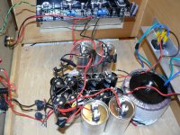
And yes I cover the power supply while adjusting the pots. You do not want to drop a screwdriver on top of those caps. I built the PS shown at the BAF F6 build where the PS is split at the final cap. I added an additional cap for each section along with a motor run cap for each channel. I build for function not looks. If this was my only amp I would definately go with a Deluxe 4U. From a brief use the amp does not run hot at all.
Variac has been asking about multiturn or single turn pots. Definitely single turn is what one wants. I first had 12 turn multi's and changed them out for single turn. Much better, at least for me. I will probably wait till tomorrow to work on the other channel.
And yes I cover the power supply while adjusting the pots. You do not want to drop a screwdriver on top of those caps. I built the PS shown at the BAF F6 build where the PS is split at the final cap. I added an additional cap for each section along with a motor run cap for each channel. I build for function not looks. If this was my only amp I would definately go with a Deluxe 4U. From a brief use the amp does not run hot at all.
Attachments
Last edited:
So could you tell us the 2 cap voltages you're using and whether the distance between the leads (pitch) is the same as the boards? And whatever else you want to add?
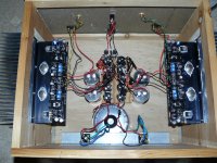
Looking at the schematic a 25V should be adequate. Test point T19 shows +14. Using a larger cap is no problem for me. Caps have long leads to suspend the cap away from everything and from what I have read it is not a good idea to put a cap directly on a board because of contracting and expansion pulling the leads of a cap. Probably never happen but.
a slight turn of P3 or P4 will make the offset go possible 20V's quickly
mmmhm, but that´s why i don´t understand the preference for singleturn pot.
anyway, both are ok for me, it´s not a critical part to purchase locally.
ah, and hey wdecho, how does it sound : ) your first channel, and all best for the other one,
stefan
So could you tell us the 2 cap voltages you're using and whether the distance between the leads (pitch) is the same as the boards? And whatever else you want to add?
I used the Elna 35V and the only only place the size did not fit perfectly was the spot in question. George Anderson of Tubelab was where I first heard not to place the caps directly on the boards but leave a little space. He adds a tiny bit of foam under his caps. Has anyone ever seen black lines on your LCD-LED TV that went away after warming up? I have heard this is caused by cap leads too tight on board, no experience only heard. I ordered the pots listed on the BOM and the 500 ohm fits perfectly, the 5K pot leads are not spaced to fit board, I made them fit by bending the leads. Just thought to add this fact, no problem really.
mmmhm, but that´s why i don´t understand the preference for singleturn pot.
anyway, both are ok for me, it´s not a critical part to purchase locally.
ah, and hey wdecho, how does it sound : ) your first channel, and all best for the other one,
stefan
My thoughts exactly when I first ordered the multipots. I found out it was too much unnecessary turning. Both will work but the multiturn ones I ordered worked in reverse of what Nelson used. The single turn did exactly as described in instructions. All Bournes. I did not listen too long on my test speakers being satisfied that I finally got one channel to work. Wish me luck on the next one. On cheap test speaker without even using a pre, just computer mp3 it did sound really good.
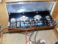
Success. If you follow the explesive instructions on biasing seasoned builders should have no problem with this build. I had one other hitch with the other channel that caused some frustration and anxiety because of builder error. Let's just say be careful with grease and getting a good solder joint. Biasing the 2nd channel was no problem after understanding what it was I was trying to do. Do use 2 meters, one attached to ground and T18 and another to set up the bias.
Many thanks again for Nelson making this project available to diyer's as myself. As for sound I only listened for one side of a LP. The bass is as good or better than anything I have heard with my horns. The jump in you chair drum roll when you hear it unexpected.
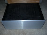
I include a picture of my F6 build to show I do know how to make a pretty amp. The store 4U is plenty good enough for this build. With the prescribed bias my amp is extremely cool.
I do need to tidy up the wires and ground all the metal parts. I lived on the edge and could not wait to hear what it sound like.
Many thanks again for Nelson making this project available to diyer's as myself. As for sound I only listened for one side of a LP. The bass is as good or better than anything I have heard with my horns. The jump in you chair drum roll when you hear it unexpected.
I include a picture of my F6 build to show I do know how to make a pretty amp. The store 4U is plenty good enough for this build. With the prescribed bias my amp is extremely cool.
I do need to tidy up the wires and ground all the metal parts. I lived on the edge and could not wait to hear what it sound like.
Attachments
Last edited:
... George Anderson of Tubelab was where I first heard not to place the caps directly on the boards but leave a little space. He adds a tiny bit of foam under his caps. ...
Do you remember in which post, or at least which thread, he said that? I am curious if the reason behind that advice is related to high-voltage operation.
- Home
- Amplifiers
- Pass Labs
- Sony vFET Amplifier Part 2