Hi Guys,
....it sang straight to my heart last night, you can really feel the emotion in the music, very pleased to have it im my system..
Cheers.
I know what you mean. 1541's are really good at this job.
Well done on the effort and congratulations on the achievement.
Will you be offering a fully populated board? I would really appreciate if you could...
Regards,
Nick
Member
Joined 2006
I know what you mean. 1541's are really good at this job.
Well done on the effort and congratulations on the achievement.
Will you be offering a fully populated board? I would really appreciate if you could...
Regards,
Nick
x2
Great job Ryanj! 😀
Thanks Guys!
Populated PCBs...
I've had a few enquiries about populated boards, and I will definitely make them available. Hoping to release them soon. This past weekend I was fine tuning, testing, and listening to make sure everything is stable and performing how it should. Looking at the list, Nick, you are second in line for a populated PCB, so I will make sure to notify you when the populated boards become available.
If you have any more questions while you wait, please feel free to ask me.
Cheers,
Ryan
Last edited:
Hello Ryan
Are you confident enough to put out the schematic now?
Hi Gopher,
Yes, at the moment feeling confident with what I have, im defiantly overdue to present some schematics. I'm hoping to complete them very soon, hopefully by the end of this week.
Once I have uploaded the schematics ill wait a few days before ordering the PCB's.
Thanks for the inquiry. 🙂
Ryan
Schematics
Hi All,
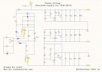
Attached are the schematics for what I have on the Distinction-1541 v2 PCB.
Ill post the Attenuator schematic soon.
PDF of full project schematics will be made available at a later date.
BOM will be posted soon.
Cheers
Hi All,
Attached are the schematics for what I have on the Distinction-1541 v2 PCB.
Ill post the Attenuator schematic soon.
PDF of full project schematics will be made available at a later date.
BOM will be posted soon.
Cheers
Attachments
more schematics
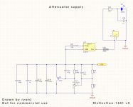
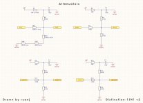
Attached are the attenuator schematics and DEM, Decoupling schematics.
Ryan
Attached are the attenuator schematics and DEM, Decoupling schematics.
Ryan
Attachments

Last edited:
Alternative values in schematics.
Hi,
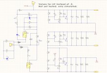
I Attached schematics of alternative values to obtain -6V instead of -5V as was done in some Philips players.
I have not tested this approach, I should though, its only 3 different values.
R26 from 1k to 1k4
R34 from 3k to 1k6
R42 from 10R to 1k
I'm not sure what to expect from this variation, anybody had experience with -6V instead of -5V?
Ryan
Hi,
I Attached schematics of alternative values to obtain -6V instead of -5V as was done in some Philips players.
I have not tested this approach, I should though, its only 3 different values.
R26 from 1k to 1k4
R34 from 3k to 1k6
R42 from 10R to 1k
I'm not sure what to expect from this variation, anybody had experience with -6V instead of -5V?
Ryan
Attachments
Thanks for sharing! I imagine you did some simulations to optimize behavior of the TL431 circuit… also some practical testing somehow?
What part do you use exactly for TL431 (X1) and Q1 in SMD?
What part do you use exactly for TL431 (X1) and Q1 in SMD?
Thanks for sharing! I imagine you did some simulations to optimize behavior of the TL431 circuit… also some practical testing somehow?
What part do you use exactly for TL431 (X1) and Q1 in SMD?
Hi Berny,
Your welcome.
The simulations I performed for these circuits were of great help and played a very integral part in the design. Compensation caps and unity gain caps were used to improve specs. I was lucky enough to have the guidance of some great teachers and engineers on this forum, one in particular was very helpful.
My practical testing was limited by the testing gear I have. Aside from probing around with a scope and doing some FFTs on basic hardware/software, there was not to much else I could do. I will eventually invest in better test gear.
Listening sessions for me always helps decide whether a circuit is good or not. I know that in the engineering world this is considered inaccurate - for a multitude of reasons. But you can't measure how enjoyable a listening experience is with electrical testing gear (that im aware of). There is always blind testing etc, but personally I still find it helpful just to listen. Plus that's most of the fun of this hobby - listening to your circuits with your favorite music to see what's changed.
The TL431 im using is NCP431 from ON Semiconductor and the PNPs are PZT2907A also from ON Semiconductor.
Cheers,
Have a good weekend Gentlemen.
Ryan
Hi Ryan,
Thanks for the elaborated answer, you listened for a difference with or without the 22uF caps (I suppose these are the unity gain caps you mention)?
I'm using a diy AYA dac and it doesn't use this kind of caps...
Thanks,
Bernard
Thanks for the elaborated answer, you listened for a difference with or without the 22uF caps (I suppose these are the unity gain caps you mention)?
I'm using a diy AYA dac and it doesn't use this kind of caps...
Thanks,
Bernard
Hi Berny,
In my simulations a 22u cap provides an output impedance of 2mohm at 22hz. Without any cap is 3.6mohm at 22hz. ~45% lower. The 22u PMLCAPs from Rubycon that are used in the circuit for AC gain look like they are some of the finest quality parts available, which should mean lower distortion in the audible freq range. The pads on the PCB for these caps could easily facilitate a substitute.
Ryan
@all
Just waiting for my CEN psu batteries to recharge then im outa here straight to the music room...
Hi Ryan, good to see your progress. it looks like you have tried many things to land here. im curious about your experiences with I/V stages. You mention the CEN, is this one of many tried that you favor?
Hi Luke,
Ive only ever experienced two different output stages (outside of a CD player). Cen has been in my system for a few years now and i've got plans to re make my pcb. The other was a shunt regulated push pull tube circuit similar to Lampizator.
Ive only ever experienced two different output stages (outside of a CD player). Cen has been in my system for a few years now and i've got plans to re make my pcb. The other was a shunt regulated push pull tube circuit similar to Lampizator.
If you make a CEN PB, I would be interested in one! A friend has a Lampizator, and I get its appeal, but I'm not sure its me. Very lush and colored, but nice. There is a thread on DIYA where someoen has refined a CCDA tube stage and I find this appealing. Although Thorsten first went with an SRPP stage, it seems the consensus from what I have seen is that it's probably not the best topology for i/v use. I think his last published i/v was a single 6922.
Ryan, I really appreciate the approach you have taken. Best engineering you could accomplish within the limits of your gear and collective experience, then actually listen and choose what sounds best to your ears.
FWIW as a long time fan of Lampizator 6n2p circuit, I can add that there is IMHO a significant difference in sound quality based on choice of resistors for both the I/V and cathode resistors. I use hand wound Manganin to great advantage over anything I could buy. I suspect similar to Rhopoint.
This is into Ryan's fine Distinction V1. I look forward to swapping in this new gem. It will mean retiring a bunch of Salas shunts currently powering V1.. but also will mean I can power down a transformer that buzzes a bit while generating +/- 5v sources. All good fun.
Wlowes, have you tried any other tube based i/v, or not looked else where? I will try and find the thread on the CCDA i/v. I think he concluded that by the time he got the i/v right, it sounded like SS. This hobby can be confusing🙂
Hi LukeWlowes, have you tried any other tube based i/v, or not looked else where? I will try and find the thread on the CCDA i/v. I think he concluded that by the time he got the i/v right, it sounded like SS. This hobby can be confusing🙂
I tried it.. liked it and have stayed with it. No doubt, lots of other great options but I have no comparative experience to report.
there's a few things I want to try with the 1541. The CCDA, and you can get I a pcb from Broskies store. I also would like to try the Pass one with jfets, name eludes me, as well as SEN. I bought a pcb for the SRPP too.
Ryan, I really appreciate the approach you have taken. Best engineering you could accomplish within the limits of your gear and collective experience, then actually listen and choose what sounds best to your ears.
FWIW as a long time fan of Lampizator 6n2p circuit, I can add that there is IMHO a significant difference in sound quality based on choice of resistors for both the I/V and cathode resistors. I use hand wound Manganin to great advantage over anything I could buy. I suspect similar to Rhopoint.
This is into Ryan's fine Distinction V1. I look forward to swapping in this new gem. It will mean retiring a bunch of Salas shunts currently powering V1.. but also will mean I can power down a transformer that buzzes a bit while generating +/- 5v sources. All good fun.
Hi Walter,
Yeah I can definitely relate.
A while back I changed gate stopper resistors in the CEN circuit from thin film to Melf - not expecting any change really. The difference was not exactly small, it was as if i'd gained some resolution. A unexpected but welcome improvement.
After trying those "naked z-foil" resistors for IV conversion in the CEN and then trying some Rhopoints, the foil resistors sounded a little grainy in comparison, although this was a long time ago and things have changed a lot in my system since, so it may be worth revisiting some time down the track.
Of course, an improperly engineered circuit with great resistors/caps is no substitute for a well engineered circuit - something I try and practice.
Cheers.
- Home
- Source & Line
- Digital Line Level
- TDA1541A Diy Pcb - "Distinction-1541 v2"