Is it wise start up amp first time without using designers right component values 🙂
Think if there is instability as with still4given's version it can reflect into DC offset trouble and maybe also hum.
Eye catch that when heat sink is not mounted into enclosure its not physical grounded and can work as antenna so maybe try connect wire from PSU ground to heat sink.
Is below C4/5 really 10uF in value think they looks physical to be much smaller in value.
Attachments
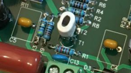
Those are 10uF 50v MLCC caps.
Instability might be it. I am using 100R gate stoppers.
I must have s mistake with resistors because the DC offset is so far off. Still4given did not have any issues with offset adjust.
Instability might be it. I am using 100R gate stoppers.
I must have s mistake with resistors because the DC offset is so far off. Still4given did not have any issues with offset adjust.
Last edited:
You have a good point there Terry. It's my first double sided through hole PCB (except for Circlophone and I have issues with that one as well). Some parts like big caps I could not solder from top and may have cold joint as result. Finally, it may be a partially bad KSA1381 as I ran out of those and had to resort to "pulled" stock from previous project. It checked out on Hfe meter but who knows if it works well enough. Fresh (non 3AM in the morning) eyes may help as well.
Need to order more 1k 1/4w resistors. Who the heck runs out of 1k resistors? 🙂
Need to order more 1k 1/4w resistors. Who the heck runs out of 1k resistors? 🙂
Last edited:
Double sided with through plated holes does take a slightly longer "heating" period when soldering. Even more important to not use a high temperature solder.
The three eutectics 37/63 and 36/62/2 silver and 36.5/62.5/1 copper are all fairly low temperature and usually work well. Except when thermal reliefs are not provided around plane pad attachments.
I usually find that the solder on the bottom side sucks in slightly just as the top side reaches melting temp. Holding or re-applying the solder in the pool until after that suck down ensures a good through hole attachment.
When you turn the PCB over you can usually see some solder around the top side lead as a result of that "suck down". It is optional to top up that top side to form a full solder meniscus cone.
Does the USA produce the 600mW metal film resistor size?...............
Need to order more 1k 1/4w resistors. Who the heck runs out of 1k resistors? 🙂
I think it is the same size as the virtually obsolete carbon film 1/4W
It fits a 0.4" pin pitch, with a body length of 6.5mm to 7mm.
I usually work with that 600mW, except when it is not available (only 5 values in the E24 range from 10r to 1M0 from my regular stockist).
Last edited:
Does the USA produce the 600mW metal film resistor size?
I think it is the same size as the virtually obsolete carbon film 1/4W
It fits a 0.4" pin pitch, with a body length of 6.5mm to 7mm.
I usually work with that 600mW, except when it is not available (only 5 values in the E24 range from 10r to 1M0 from my regular stockist).
I just ordered some Vishay 600mW 1k 1% from Digikey. Also some Murata np0 10pF caps 5mm pitch. Some guaranteed genuine Fairchild KSA1381 and KSC3503 because I ran out. 🙂 also some Stackpole 15k 1% metal film 0.25w resistors.
The KSA and KSC's were not too bad - $3.50 for qnty 10. Should last me a few more amp projects.
Oh it pains me to pay US distributor prices but I get it in 2 days. 😀
Last edited:
Double sided with through plated holes does take a slightly longer "heating" period when soldering. Even more important to not use a high temperature solder.
The three eutectics 37/63 and 36/62/2 silver and 36.5/62.5/1 copper are all fairly low temperature and usually work well. Except when thermal reliefs are not provided around plane pad attachments.
I usually find that the solder on the bottom side sucks in slightly just as the top side reaches melting temp. Holding or re-applying the solder in the pool until after that suck down ensures a good through hole attachment.
When you turn the PCB over you can usually see some solder around the top side lead as a result of that "suck down". It is optional to top up that top side to form a full solder meniscus cone.
Thanks for the tip. I am using 60/40 solder with 1.3% rosin core content, 0.8mm dia. Seems to flow well. I am also looking for the suck down and it happens at about 5 to 6 seconds after applying heat and seeing initial melt. I also look for meniscus on other side and then finish off with solder iron tip to reflow if not a meniscus. But this can't be done on caps that sit flush and block upper access (elco's and trim pots).
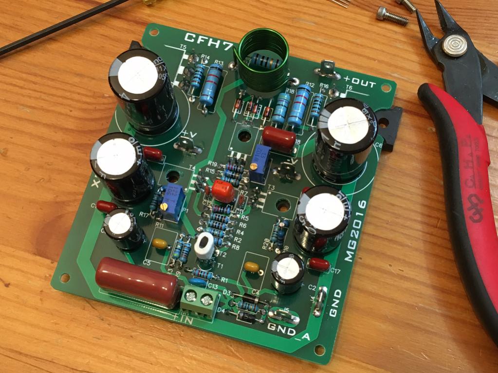
Every time to see a layout coming to live....
Marc
Marc,
Thanks for a wonderfully easy to build and great looking design. I had to drill out the screw holes for the TO126's to fit a 4-40 hex head cap screw. I actually used a centering countersink drill bit and did it post facto with transistor installed underneath. Slow and steady on drill press resulted in perfect hole without touching said transistor underneath. 😀.
Like these (they drill FRP very smooth and clean):

A Dremel tool mini drum sander attachment took care of the little cutout for mounting the big MOSFETs. That was easy work with Dremel tool.
With 5 transistors screwed to heatsink I found no need for corner standoffs. It's very secure.
Last edited:
I have a real humdinger of a problem for you guys: both of my boards are exhibiting this very strange behavior:
When connected to the DAC as source the bias current adjustment works fine but the DC offset runs out of room at 0.8v and there is mild 60Hz hum. Music sounds good if played loud to overcome hum background. Can run 150mA or 200mA bias fine.
When DAC is disconnected and inputs shorted with a wire, DC offset adjusts to zero just fine, but bias current adjust has NO EFFECT. Nothing. And bias current defaults to piddly 1mA or less across 0.22R Supply resistor and 6mA globally as measured through rail safety resistor.
When CD player connected same as short, DC bias can be set to zero, hum is gone, bias is zero (6mA global) and unadjustable. Music has terrible xo distortion when played.
Checked voltage on audio input +ve pin with DAC connected - it is +0.25v! It's AC coupled so where does DC come from? DAC measures 1mV DC by itself but 0.25V connected. Also, global current (some of which is bias) magically jumps up from 6mA to previously set 180mA when DAC input is connected and DC offset jumps to 0.8v.
DAC is powered by un grounded center tap trafo for analog op amp section and 9vac separate trafo for DAC portion. Trafos for DAC and main amp toroid connected to same mains terminal block.
This is same setup I use for all my other dozen amps. Never had a wierd ground loop like this. I even tried bypassing separate grounds on amp with jumper and no effect.
One more clue. When connected to DAC and it plays music, there is asymmetry in supply rails usage as safety resistor on +ve rail shows higher value of current than negative rail by 4x.
What a puzzle. I tried changing Vbe multiplier transistors, new pots for bias adjustment and new pot for offset. Checked all resistor values and correct. It's happening identically to both boards so I think something must be strange in how this board is laid out or connected.
Other clue is Sonal's layout did not have problem. What am I supposed to be doing with the separate ground pins on the amp? I have them connected together on the board with a 12ga piece is solid copper soldered between bus traces at present.
I verified with Ohm meter that input caps do not conduct - not shorted. I even removed MLCC 10uF thinking it might be bad and left Panasonic 3.3uF 250v MKT in place. That cap is good one - definitely no DC across it. Also looked carefully at input traces - only connection to cap is via the trace that goes to input stage to 22k to ground and 330pF to ground before going to shared base of T1 and T2.
Last edited:
Is the DAC injecting HF that is upsetting the amplifier?
What frequency have you set your RF attenuator filter to?
The sch in post247 does not show an effective RF filter !
What is the preceding impedance that is provided by the interconnect cable?
What frequency have you set your RF attenuator filter to?
The sch in post247 does not show an effective RF filter !
What is the preceding impedance that is provided by the interconnect cable?
Last edited:
I suppose I am missing the usual series 2.2k between input and base of T1. That doesn't explain why when input is shorted that I can't adjust bias current on amp. The DAC output impedance I will have to check but it's a CS4398 with a Birr Brown OPA2604 output op amp that I believe goes through a 10uF elco before exiting the DAC board.
What am I supposed to be doing with the separate ground pins on the amp? I have them connected together on the board with a 12ga piece is solid copper soldered between bus traces at present.
If I understand correctly, you do not have a connection between the signal ground and power ground on each amp board, right?
The output must be referenced to the same voltage as the input.If I understand correctly, you do not have a connection between the signal ground and power ground on each amp board, right?
Are you the first person to build this layout? Maybe there is an error in the layout. Sounds like a grounding issue. Do you have a separate ground wire from input ground to star ground?
Is this the layout fromposthttp://www.diyaudio.com/forums/solid-state/294834-cfh7-amp-4.html#post4803910 173? It looks like the ground for the entire amp is attached through the ground lift at the input. First thing I would try is shorting that ground lift. If that works we can go from there.
- Home
- Amplifiers
- Solid State
- CFH7 Amp