thanks hugh, terry & minek123 for the correction, much appreciated.
Attachments
Last edited:
Is the blue LED connected the right way?
yep.
the PCB is wrong . you're right
Thiago
yep.
the PCB is wrong . you're right
Thiago
cathode of blue led goes to anode of D7 and anode of blue led goes to cathode of D7.
Wonder what would happen if we use a IRFP250 instead of IRFP240. It has slightly higher dissipation and higher current rating. But its Ciss is higher too. Will that affect it audibly ?
No, Ashok, the drive will be sufficient even though the 250 has 230W rating compared to the 240 which is around 150W. The 240 has Rdson of 0.18R, current of 12A cont and 39nC gate charge, while the 250 has 0.085R, 19A cont and 74nC gate charge. This charge is with respect drain, which sits at AC ground since it is a rail supply. This hikes up and down under drive of the gate circuitry, and 74nC is pretty small as long as the voltage amp drive is around 8mA or more. These gate charges are significant at 1MHz, but not important up to 20KHz. We are not fruit bats, so we hear it very well......
The Rdson is important, however. 85 milliohms is a lot less than 180milliohms, and it will improve the damping factor. Effectively it would make the amp sound rather larger, the scale would be bigger, since is can move the speaker a little more easily. These are subjective comments; you may not like them! But if you increase the nmos, will you also increase the npn, maybe to a LAPT transistor like the Sanken? Then you can increase the rail voltages, maybe to 50-60V, no?
Are you moving to another city, Sire?
Cheers,
Hugh
No, Ashok, the drive will be sufficient even though the 250 has 230W rating compared to the 240 which is around 150W. The 240 has Rdson of 0.18R, current of 12A cont and 39nC gate charge, while the 250 has 0.085R, 19A cont and 74nC gate charge. This charge is with respect drain, which sits at AC ground since it is a rail supply. This hikes up and down under drive of the gate circuitry, and 74nC is pretty small as long as the voltage amp drive is around 8mA or more. These gate charges are significant at 1MHz, but not important up to 20KHz. We are not fruit bats, so we hear it very well......
The Rdson is important, however. 85 milliohms is a lot less than 180milliohms, and it will improve the damping factor. Effectively it would make the amp sound rather larger, the scale would be bigger, since is can move the speaker a little more easily. These are subjective comments; you may not like them! But if you increase the nmos, will you also increase the npn, maybe to a LAPT transistor like the Sanken? Then you can increase the rail voltages, maybe to 50-60V, no?
Are you moving to another city, Sire?
Cheers,
Hugh
hi Hugh .
R20 and R21 is the value that influences the damping factor ?
0R47 will give less damping factor ?
I would like to test with less damping factor ...
Regards
Thiago
If you are using +-42V rails you should be fine with 50V caps. You don't have the blue LED connected right. It should connect to the same place as Zener but reversed.
Hey guys, Terry found it earlier 😀
Last edited:
Hi Thiago,
Yes, actually correct, but the Rdson adds to the source resistor on the mosfet, then is divided by the feedback factor. So, for the IRFP240, (0.18 + 0.33)/38 = 0.013R. This is theoretically, using simple math, but in reality the AC conditions are a little different and you would expect to have a Zout around 80 milliohms or so, which is a DF of 100. And of course this figure varies with frequency and output level. Be careful; too much DF gives huge control over bass and some people do not like the sound because the decay of notes is badly affected. I try to shoot for 50 or LESS 🙁
Greg,
Hi hombre, how are things? You are right; Terry actually built it and tested it! 😀
Hi Thiago,
Yes, actually correct, but the Rdson adds to the source resistor on the mosfet, then is divided by the feedback factor. So, for the IRFP240, (0.18 + 0.33)/38 = 0.013R. This is theoretically, using simple math, but in reality the AC conditions are a little different and you would expect to have a Zout around 80 milliohms or so, which is a DF of 100. And of course this figure varies with frequency and output level. Be careful; too much DF gives huge control over bass and some people do not like the sound because the decay of notes is badly affected. I try to shoot for 50 or LESS 🙁
Greg,
Hi hombre, how are things? You are right; Terry actually built it and tested it! 😀
Thank you Hugh .
I played with ACA Nelson Pass and I like low DF and bass more " loose "
I'll try 0R47 and see the result .
Regards
Thiago
thanks hugh, terry & minek123 for the correction, much appreciated.
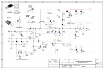
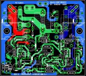
Hi Dacz, may I ask what program you are using drawing the schematics and PCB layout, it looks nice, especially with the inserted graphical 3D pictures of various transistor packages in the upper left corner of the schematics. 🙂
........Are you moving to another city, Sire?..............
Hi Hugh,
Yes I'm moving to another city. Supposed to have moved in July but various things delayed it and now I'll hopefully move by the end of this month. To add to all of it I fell flat on my face last night on the main road. Tripped on uneven bitumen layers. Have a slight scrape on my knees but thankfully nothing bad happened. I'm no spring chicken so such things can be very dangerous !
Thanks for that note on the IRFP250. I did think about the need to increase the capacity of the npn. I have two pairs of Sankens but that was for a different project. I feel inclined to use the 250 with maybe 2 npn's ? They will have to be closely matched I guess. But that isn't hard to do compared to getting more genuine Sankens ! Plenty of things to do soon after I move.
I should start on the pcb design if I get time. Currently I am stuck with packing duties and that takes a lot of time. Will be interesting if the 4 ohm rating can be increased significantly . Pity, it will take time . I won't even have a proper work bench for some time to come ! 😡
Hi Dacz, may I ask what program you are using drawing the schematics and PCB layout, it looks nice, especially with the inserted graphical 3D pictures of various transistor packages in the upper left corner of the schematics. 🙂
Sprint6 for layout and Splan7 for schematic
Hi guys,
As this post is progressing, can you (the designers) conclude that the design is a go or is it still being tuned with some expected value changes..?
XRK send us his as-built schematic and earlier Bangla H provided us a quick BOM. I used Bangla's BOM and created a simple Word file with an added colomn for the XRK as built values. There is also a third colomn which could be the final value and also some recommandation, ex ; Bootstrap cap to be Nichicon KZ, Feedback cap to be Elna Silmic II...you get the point.
Also, what is the recommended rails supply for this amp ? Is there a range ex +/-35 to +/- 42Vdc, also, what is the expected output power so we can properly size the PSU.
Thanks,
Eric
Attachments
Hi Eric,
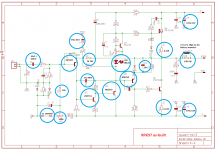
I have examined this and my thoughts are the a few values could be changed to optimise the harmonic profile based on what people have experimented with and auditioned:
C4 feedback shunt cap 470uF SHOULD BE 1000uF (more bass)
Q2 VAS master 2N5551 SHOULD BE KSA1845 (more bandwidth, higher beta)
Q3 VAS buffer MJE350 SHOULD BE KSA3503 (more bandwidth)
D7 Voltage Reference Blue LED SHOULD BE 3.3 ZENER (better tempco and not bright!)
C9 Bax cap 20nF filmcap SHOULD BE 22nF (20nF is not a npv)
R20/R21 OPS source/emitter resistors 3W wirewound SHOULD BOTH BE 0.33R (extends the conduction angle of Q6 nmos and improves stability of OPS quiescent current)
These are my beliefs for this amp, I will be building this too, and my voltage rails will be 42V, the absolute maximum for IRFP240 and 2SC5200.
If you want more power, up to 62V rails which will give you 200W, I would suggest a FQA40N15 nmos and a 2SC3264 Sanken, 280W and 200W respectively.
Hugh
Thank you very much Hugh !
I have a single 600W SMPS from Cresnet rated +/-40Vdc, this will be perfect for a stereo amp.
Can someone confirm the required bias..is it around 100mA ?
BR,
Eric
I have a single 600W SMPS from Cresnet rated +/-40Vdc, this will be perfect for a stereo amp.
Can someone confirm the required bias..is it around 100mA ?
BR,
Eric
Hugh, I agree 100%
Eric, I set the bias a little higher at around 150mA but 100mA is adequate.
Eric, I set the bias a little higher at around 150mA but 100mA is adequate.
Christian,
Thank you...... considering you've been listening to the proto you designed for almost a years!!
Eric,
Yes, 125mA to 150mA. It will get hot, so allow plenty of cooling.
I would be interested in your thoughts on the sound with a smps. I have done this experiment with my amps, and come to a conclusion........
Hugh
- Home
- Amplifiers
- Solid State
- Very simple quasi complimentary MOSFET amplifier