Gerbers on post 109 in case you missed it. Shipping boards from USA abroad would cost almost as much as you ordering your own from HK. 🙂
http://www.diyaudio.com/forums/solid-state/294834-cfh7-amp-11.html#post4795571
http://www.diyaudio.com/forums/solid-state/294834-cfh7-amp-11.html#post4795571

Sonal, wonderful layout as usual.
Aesthetically, it's very "muscular" looking - vey cool indeed. 🙂
10uF can be usual tiny radial leads electrolytic we always use on Apex amps that I bypass with 100nF 100v manually with soldering to legs of electrolytic. Also, use of huge 10uF MKT 250v (25mm radial lead spacing) works but those are so big. Sort of like on FX8 Bimo.
Thanks !
Last edited:
Both boards are esthetically and it needs a transparent cover that we can look inside
the Amp, every time we wish to do.
the Amp, every time we wish to do.
Both boards are esthetically and it needs a transparent cover that we can look inside
the Amp, every time we wish to do.
All my amps are never covered so I can enjoy looking at them. (or is it simply because I have too many amps and can't figure out which to put in a covered box?) 🙂
These boards, when realized in fiberglass and copper, will look and, I predict, sound SUPER. 😀
Sonal,
Thank you for the beautiful layout. A work of art!
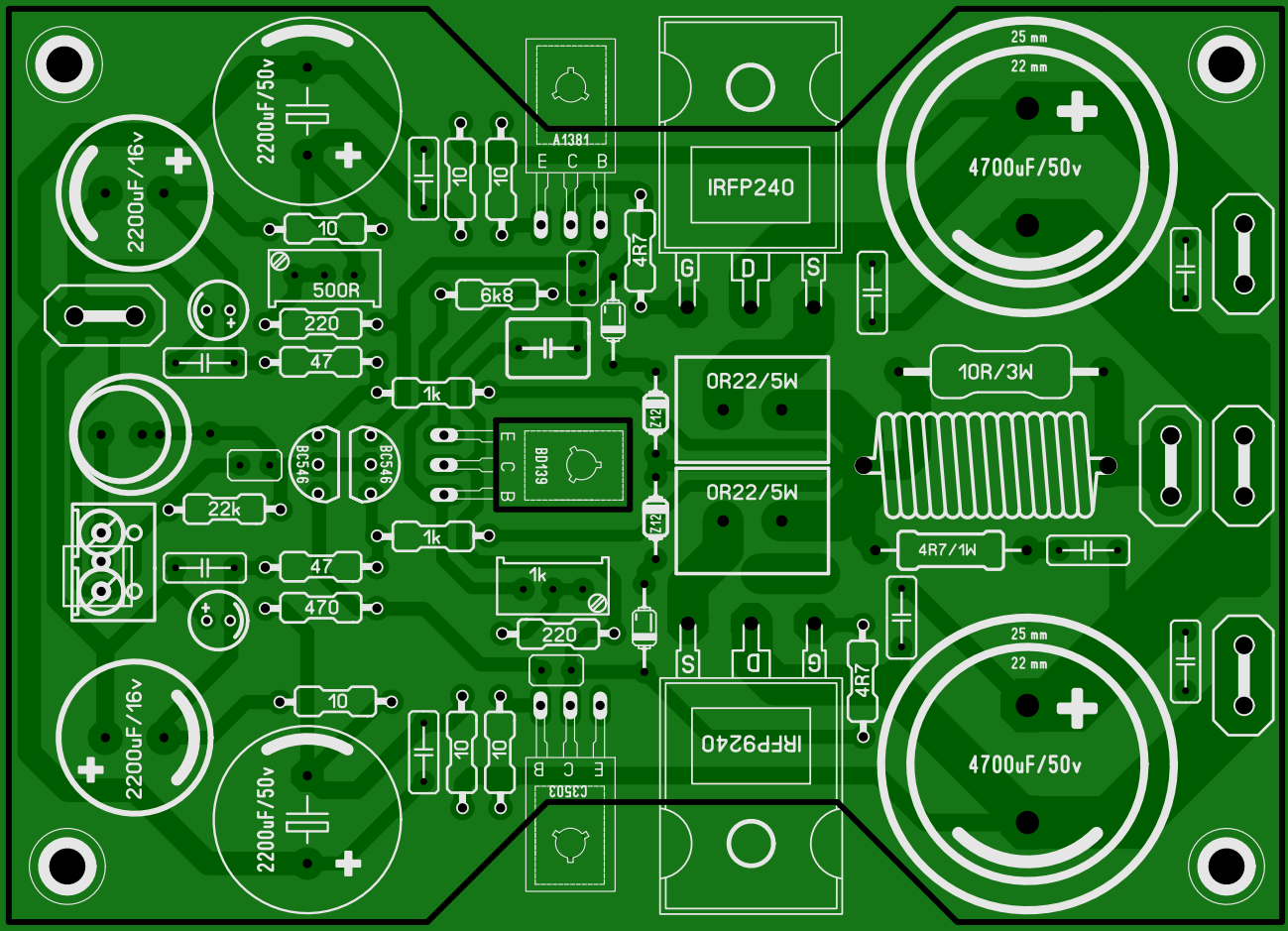
Do you mean to have the board cut out with an hourglass shape as shown by black outline for access to mounting screws on transistors - versus drilled holes in rectangular board? The shape makes it very distinctive and cool to be non-rectangular. What are the overall dimensions?
Thank you for the beautiful layout. A work of art!
Do you mean to have the board cut out with an hourglass shape as shown by black outline for access to mounting screws on transistors - versus drilled holes in rectangular board? The shape makes it very distinctive and cool to be non-rectangular. What are the overall dimensions?
Last edited:
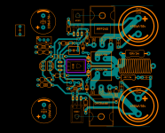
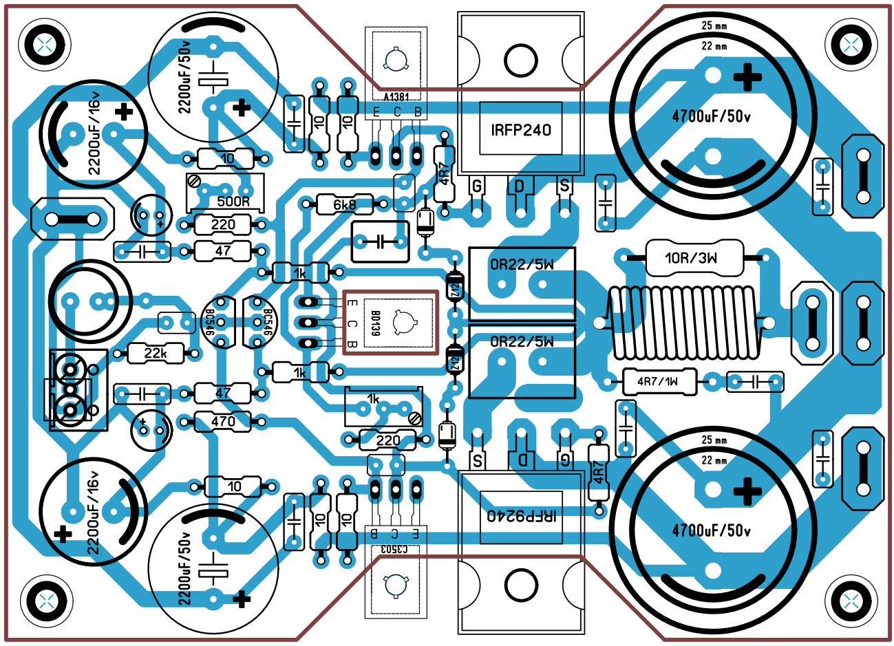
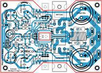
this layout of the power input and the output stage is far better than the majority of layouts we see being posted on this Forum.Finished layout of CFH7. I'll make revisions tomorrow, need fresh mind for finding mistakes.
Look at the three power input terminals. Close together ready to receive the power cable twisted triplet.
Close spacing of the speaker cable output and return, again suiting the twisted pair.
Look carefully at the route taken by the +ve halfwave from +ve power through the power FET to the speaker output. Small area loop. Now compare the route taken by the -ve halfwave, again a small loop area. This results in low EMI being emitted to be picked up by the input stages.
Importantly this small loop includes a power return trace that does NOT pass around the low level circuits.
Last edited:
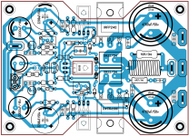
The two small local decoupling capacitors to the right of the 4700uF do not have trace connections to the supply traces.
I can't find the low impedance connection that allows the output to voltage reference to the input.
Is it worth squeezing in a separate spade for the speaker return cable?
Add some alternative pin pitch options for the small caps where you have space. Particulary the output Zobel cap 0.2", 0.3", 0.4"
I recommend that the 4r7 Zobel resistor be increased to substantially higher than 1W. Maybe 3W or 5W
Last edited:
The two small local decoupling capacitors to the right of the 4700uF do not have trace connections to the supply traces.
I can't find the low impedance connection that allows the output to voltage reference to the input.
I agree - was looking for it too and looks like there are simply two separate grounds right now. One for input stage on one end of board and one for output end of board. I think Shaan PeeCeeBee may have been that way with no resistor and diodes.
I think Idefixes layout also has a small current loop with output stage - just not all connectors next to each other. Sometimes that is good to prevent inadvertent shorts between power leads if one doesn't use insulated female FASTONs.
The Idfixes post103 I see has a very long ground trace that loops right around the circuit board spraying power EMI into everything inside the loop..................
I think Idefixes layout also has a small current loop with output stage - .............
So you are saying that the big ground U shape should have been flipped 180deg to go around the power end of the board? How much EMI spray are we talking about from a ground bus? If the ground bus is kept sufficiently low impedance by making it wide - the voltage developed across it would be fairly low and EMI is function of voltage/distance, correct?
Finished layout of CFH7. I'll make revisions tomorrow, need fresh mind for finding mistakes.
Just a by-passer here, I also think you have made brilliant layout, Andrews analysis is spot on and it was also my first impression how nicely you have lay-outed the high current power supply paths.
 🙂
🙂CFH9
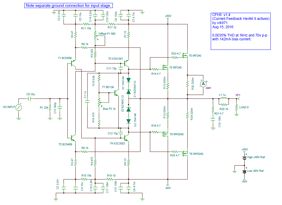
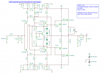
What do you guys think of 70v p-p output with 0.0035% THD at 1kHz? 60 volt rails required but layout looks like the F1 car design from Sonal just needs to be elongated to stuff another pair of cylinders to hot rod this ride.
We are probably right at the edge of the SOA as this is circa 300w. But for an extra $2 of MOSFETs, it sure is an exciting ride. 🙂
Schematic v1.04:
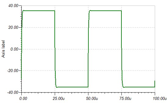
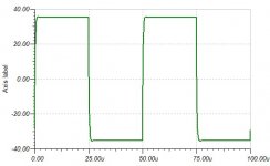
Square wave at 20kHz with 70v p-p:
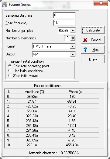
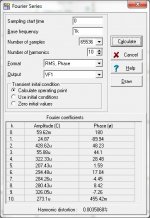
FFT analysis for distortion components, note that 2nd and 4th harmonic are dominant over 3rd and 5th so the sound should have a pleasant harmonic profile:
What do you guys think of 70v p-p output with 0.0035% THD at 1kHz? 60 volt rails required but layout looks like the F1 car design from Sonal just needs to be elongated to stuff another pair of cylinders to hot rod this ride.
We are probably right at the edge of the SOA as this is circa 300w. But for an extra $2 of MOSFETs, it sure is an exciting ride. 🙂
Schematic v1.04:
Square wave at 20kHz with 70v p-p:
FFT analysis for distortion components, note that 2nd and 4th harmonic are dominant over 3rd and 5th so the sound should have a pleasant harmonic profile:
Attachments
Last edited:
Thanks all of you for support and encouragement.
Latest revision, made changes on suggestion from AndrewT.
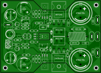
Board will be cut as shown by outline by pcb manufacturer, also square hole will be cut for BD139. But for those who will diy pcb they have to make rectangular board I'll post pdf of rectangular version.
Latest revision, made changes on suggestion from AndrewT.
Do you mean to have the board cut out with an hourglass shape as shown by black outline for access to mounting screws on transistors - versus drilled holes in rectangular board? The shape makes it very distinctive and cool to be non-rectangular. What are the overall dimensions?
Board will be cut as shown by outline by pcb manufacturer, also square hole will be cut for BD139. But for those who will diy pcb they have to make rectangular board I'll post pdf of rectangular version.
Attachments
C3503 no 10 ohms resitor from emitter to negative rail and why 10 ohms from negative
rail to base of TR3503
Hello Sonal
greetings very nice pcb design can you post lay files if possible
warm regards
Andrew
rail to base of TR3503
Hello Sonal
greetings very nice pcb design can you post lay files if possible
warm regards
Andrew
- Home
- Amplifiers
- Solid State
- CFH7 Amp