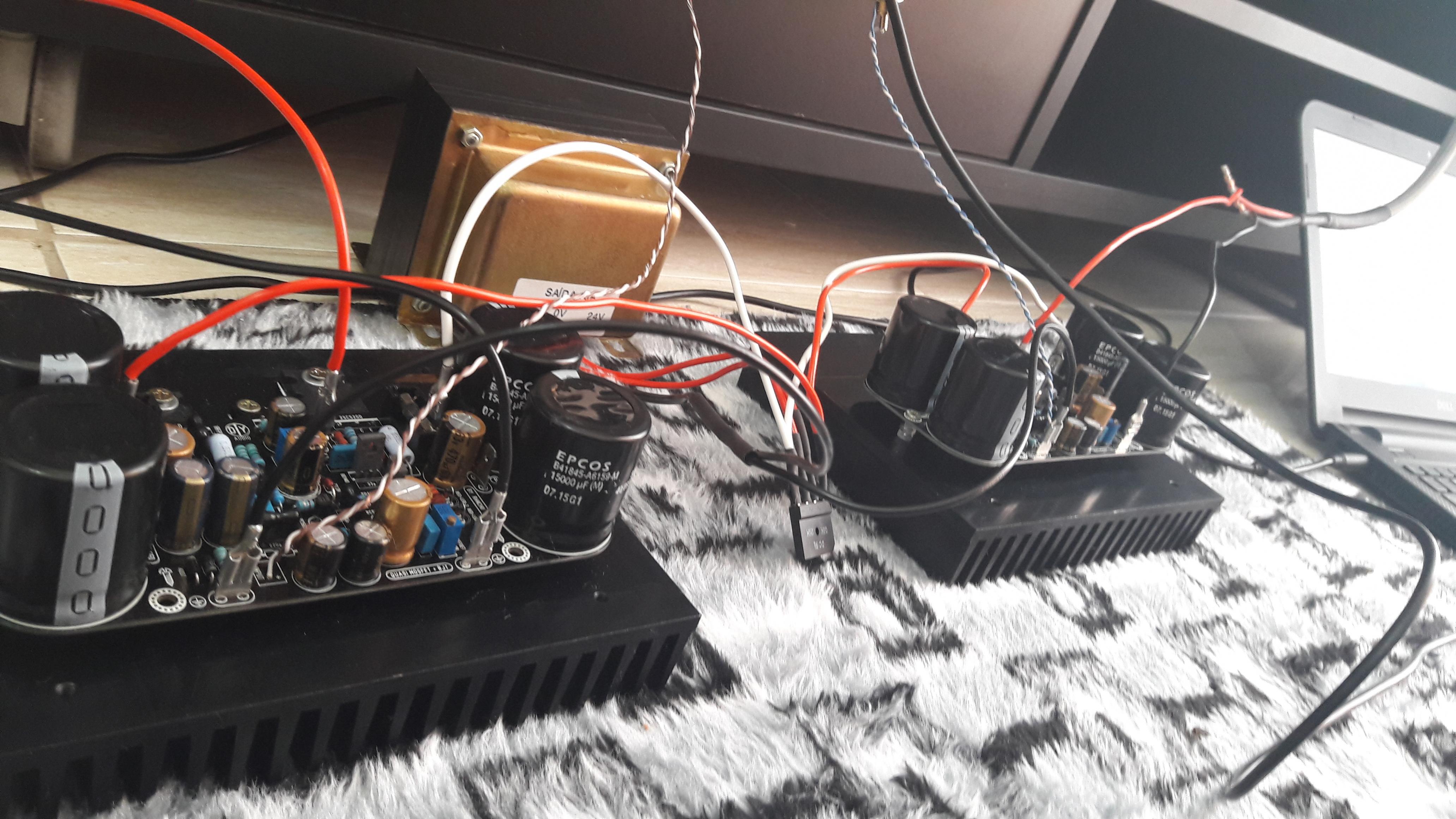
first sound test on my main system.
Simply the best amp I have.
Sweet and profound to summarize .
Thank you friends for this amazing amp .
Greetings .
Thiago
There is that Sweet word again 🙂
Congratulations Thiagomogi on a fine looking (and sounding) amp!

thiagomogi,
Looking forward to more of your listening impressions of this amplifier and hopefully PCB's to build it. 🙂
Looking forward to more of your listening impressions of this amplifier and hopefully PCB's to build it. 🙂
question: going 2oz copper, will alleviate the trace lift problem encountered by XRK while desoldering?
tried to 470uF the C4 , I like 2x1000uF in my listening tests .
I do not need Cap DNI .
C5 22pF and is stable .
I will keep C3 and C6 in 470uF because I will use dc and delay protection.
I have 50 mV at R20 .
Any suggestion?
Regards
Thiago
I do not need Cap DNI .
C5 22pF and is stable .
I will keep C3 and C6 in 470uF because I will use dc and delay protection.
I have 50 mV at R20 .
Any suggestion?
Regards
Thiago
question: going 2oz copper, will alleviate the trace lift problem encountered by XRK while desoldering?
I would say yes, as I went on to build another amp (Apex AX11) made using double thickness (70um) copper and it is very durable. I did a few desoldering changes and had no issues. Any solder points on a wide ground plane though needs a lot of watts to heat up before solder will flow though. This is why sometimes small heat conduction reduction cutouts are added to pads on wide strips of copper.
The problem with 2oz copper is the price is 5x more than 1oz ($50 vs $10) for 10 boards.
I will consider then a controlled heat iron, and if I err something, a desoldering braid...The problem with 2oz copper is the price is 5x more than 1oz ($50 vs $10) for 10 boards.
Thiago, those fantastic heatsinks are from a brazilian manufacturer, or are imports?first sound test on my main system.
Simply the best amp I have.
Sweet and profound to summarize .
Thank you friends for this amazing amp .
Greetings .
Thiago
Path - minus C7 to D7 Anode moved
Hallo.
So many many impressive information last days here- many to work up.
Holy Moly !
I have seen the connection from minus C7 has moved to Anode of D7- so
i have to brake conducting path to Trimmer/Emitter Q4 point.
In this position must placed a little wire now- not other way to solve 4.1
Board.
happy listening to successful Builder !
I have 50 mV at R20tried to 470uF the C4 , I like 2x1000uF in my listening tests .
I do not need Cap DNI .
C5 22pF and is stable .
I will keep C3 and C6 in 470uF because I will use dc and delay protection.
I have 50 mV at R20 .
Any suggestion?
Regards
Thiago
Is this adjustable by the VR2?
I have 50 mV at R20
Is this adjustable by the VR2?
Yes, I have the perfect VR2 configuration work .
My question is should I try something else ?
You guys are running 150mA bias current? Pretty warm there - perhaps the sound is better than 100mA?
33-45 mV on R21 is AKSA suggestionYes, I have the perfect VR2 configuration work .
My question is should I try something else ?
Thiago, those fantastic heatsinks are from a brazilian manufacturer, or are imports?
Made in Brazil
🙂
Hi Thiago,
Very pretty amp, congratulations!!
Can you describe the difference with 2,200uF versus 470uF?
Hugh
Very pretty amp, congratulations!!
Can you describe the difference with 2,200uF versus 470uF?
Hugh
I built the new boards with the changes from post #1032. I am out of range on the bias. I can get one board down to 100mA but the lowest on the other is 150mA. That is with the trimmer at 1k. Sine waves look good and offset looks solid though I didn't let it run for very long.
Thank you Thiago,
Do you think 1000uF would be a compact,
economical solution with 1k8/68R?
You could get away with a small 6.3VW
C4 as well.....
Terry,
Change R13 from 1k2 down to 820R.
This brings back the range well below 100ma.
Damn quick!
Hugh
Do you think 1000uF would be a compact,
economical solution with 1k8/68R?
You could get away with a small 6.3VW
C4 as well.....
Terry,
Change R13 from 1k2 down to 820R.
This brings back the range well below 100ma.
Damn quick!
Hugh
Last edited:
I had it built hours ago but have spent a lot of ltime trying to find the mistake that was causing the high bias. I finally decided that I had no mistakes so post the results here. I change the resistor and get back to you.
Thanks, Terry
Thanks, Terry
Hi HUgh,
That was the ticket. Playing music as I type this. I'm going to let it play for about an hour and recheck the bias and offset. I put little TO92 heatsinks on Q1 so we'll see if that helps anything.
That was the ticket. Playing music as I type this. I'm going to let it play for about an hour and recheck the bias and offset. I put little TO92 heatsinks on Q1 so we'll see if that helps anything.
hugh,
yes, I think 1000uF can be perfect , I'll try .
Terry , if you can compare with FX8 I would be happy .
Regards
Thiago
yes, I think 1000uF can be perfect , I'll try .
Terry , if you can compare with FX8 I would be happy .
Regards
Thiago
- Home
- Amplifiers
- Solid State
- Very simple quasi complimentary MOSFET amplifier